Common mode noise filter

a common mode and filter technology, applied in the direction of current interference reduction, line-transmission details, electrical equipment, etc., can solve the problems of communication sensitivity degrading, insufficient insertion of a common mode filter into a pair of signal lines, etc., to reduce the height of a product, prevent an increase in production cost, and reduce the planar size of the componen

Active Publication Date: 2011-11-24
TDK CORPARATION
View PDF2 Cites 15 Cited by
  • Summary
  • Abstract
  • Description
  • Claims
  • Application Information

AI Technical Summary

Benefits of technology

[0010]In the present invention, a configuration may be adopted in which the pair of coils are formed in a single component, and common mode filter and the pair of coils are formed respectively in different components. With this arrangement, it is possible to remove differential mode noise in a desired frequency band without modification to an existing common mode filter.
[0023]As described above, according to the common mode noise filter of the present invention, it is possible to remove not only common mode noise but also differential mode noise in a desired frequency band.

Problems solved by technology

Thus, the insertion of a common mode filter into a pair of signal lines may be insufficient for noise reduction.
In particular, when a signal line in a mobile phone serves as a generation source of the differential mode noise, communication sensitivity may degrade.

Method used


Image

  • Common mode noise filter
  • Common mode noise filter
  • Common mode noise filter

Examples


first embodiment

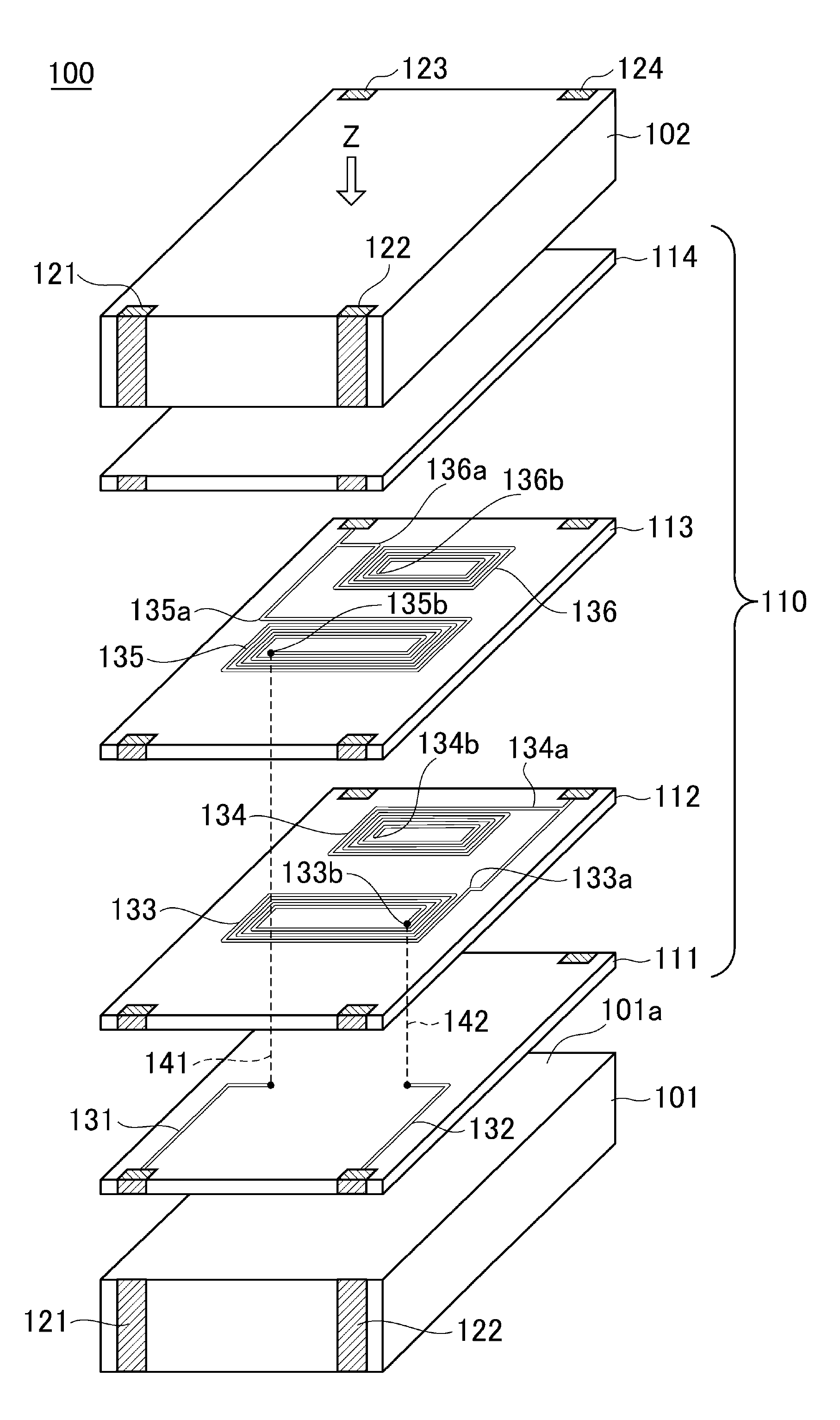
[0063]FIG. 5 is a perspective view schematically illustrating the outer appearance of a common mode noise filter 100 according to the present invention.

[0064]As illustrated in FIG. 5, the common mode noise filter 100 according to the present embodiment is so-called a surface mount type chip component and includes magnetic substrates 101, 102 and a functional layer 110 sandwiched by the magnetic substrates 101 and 102. Further, four terminal electrodes 121 to 124 are formed on the outer circumferential surface of a stacked body constituted by the magnetic substrate 101, functional layer 110, and magnetic substrate 102. The magnetic substrates 101 and 102 each play a role of physically protecting the functional layer 110 and serves as a closed magnetic path of the common mode filter. As a material of the magnetic substrates 101 and 102, a sintered ferrite, a composite ferrite (resin containing ferrite powder) or the like can be used. It is particularly preferably to use a sintered fer...

second embodiment

[0080]FIG. 9 is a transparent perspective view schematically illustrating only conductive patterns included in the functional layer of a common mode noise filter 200 according to a

[0081]As illustrated in FIG. 9, in the common mode noise filter 200 according to the second embodiment differs from the abovementioned common mode noise filter 100 in that the winding direction from the outer circumferential end of the coil pattern 134 to the inner circumferential end thereof as viewed in Z direction is clockwise direction, and the winding direction from the outer circumferential end of the coil pattern 136 to the inner circumferential end thereof as viewed in Z direction is counterclockwise direction. The other points are the same as those in the common mode noise filter 100. Accordingly, the same components are denoted by the same reference numerals, and overlapping descriptions are omitted.

[0082]With the above configuration, the coil patterns 134 and 136 are magnetically coupled to each...

third embodiment

[0084]As illustrated in FIG. 10A, in the common mode noise filter 300 the winding direction from the outer circumferential end of the coil pattern 134 to the inner circumferential end thereof as viewed in Z direction is counterclockwise direction, and the winding direction from the outer circumferential end of the coil pattern 136 to the inner circumferential end thereof as viewed in Z direction is also counterclockwise direction. However, the coil pattern 134 is connected, at its inner circumferential end 134b, to the terminal electrode 124, and the outer circumferential end 134a is opened. The other points are the same as those in the common mode noise filter 100. Accordingly, the same components are denoted by the same reference numerals, and overlapping descriptions are omitted.

[0085]With the above configuration, the coil patterns 134 and 136 are magnetically coupled to each other in the opposite directions. Therefore, the common mode noise filter 300 according to the present e...


PUM


Abstract

A common mode noise filter includes: a common mode filter inserted into a pair of signal lines; and a pair of capacitively coupled coils having one ends connected respectively to the corresponding signal lines and the other ends opened. According to the present invention, common mode noise can be removed by a common mode filter, as well as, differential mode noise in a desired frequency band can be removed by a pair of coils whose other ends are opened.

Description

BACKGROUND OF THE INVENTION[0001]1. Field of the Invention[0002]The present invention relates to a common mode noise filter and, more particularly, to a common mode noise filter capable of attenuating not only common mode noise but also differential mode noise in a specified frequency band.[0003]2. Description of Related Art[0004]In recent years, USB 2.0 standard or IEEE1394 standard has been widely spread as a high-speed signal transmission interface and is now used in various kinds of digital devices such as a personal computer and a digital camera. Such an interface adopts a differential transmission system that transmits a differential signal using a pair of signal lines and realizes higher-speed signal transmission than a conventional single-end transmission system.[0005]As a filter for removing noise on a high-speed differential transmission channel, a common mode filter is often used (refer to Japanese Patent Application Laid-Open No. H8-203737). The common mode filter has lo...

Claims


Application Information

Patent Timeline
Patent Type & Authority Applications(United States)
IPC IPC(8): H03H7/01
CPCH03H7/09H03H7/48H04B3/28H03H7/427H03H2001/0085
Inventor NAKAGAWA, TAKASHIOKUMURA, TAKESHITOMONARI, TOSHIO
Owner TDK CORPARATION
Why Eureka
Try Eureka