
Forward-looking 3D imaging radar and method for acquiring 3D images using the same

a 3d imaging and radar technology, applied in the direction of reradiation, measurement devices, instruments, etc., can solve the problems of difficult to implement exact time delay for a short time by using rf delay, and difficult to actual implement hardwar

Active Publication Date: 2011-11-24
AGENCY FOR DEFENSE DEV
View PDF11 Cites 16 Cited by
  • Summary
  • Abstract
  • Description
  • Claims
  • Application Information

AI Technical Summary

Benefits of technology

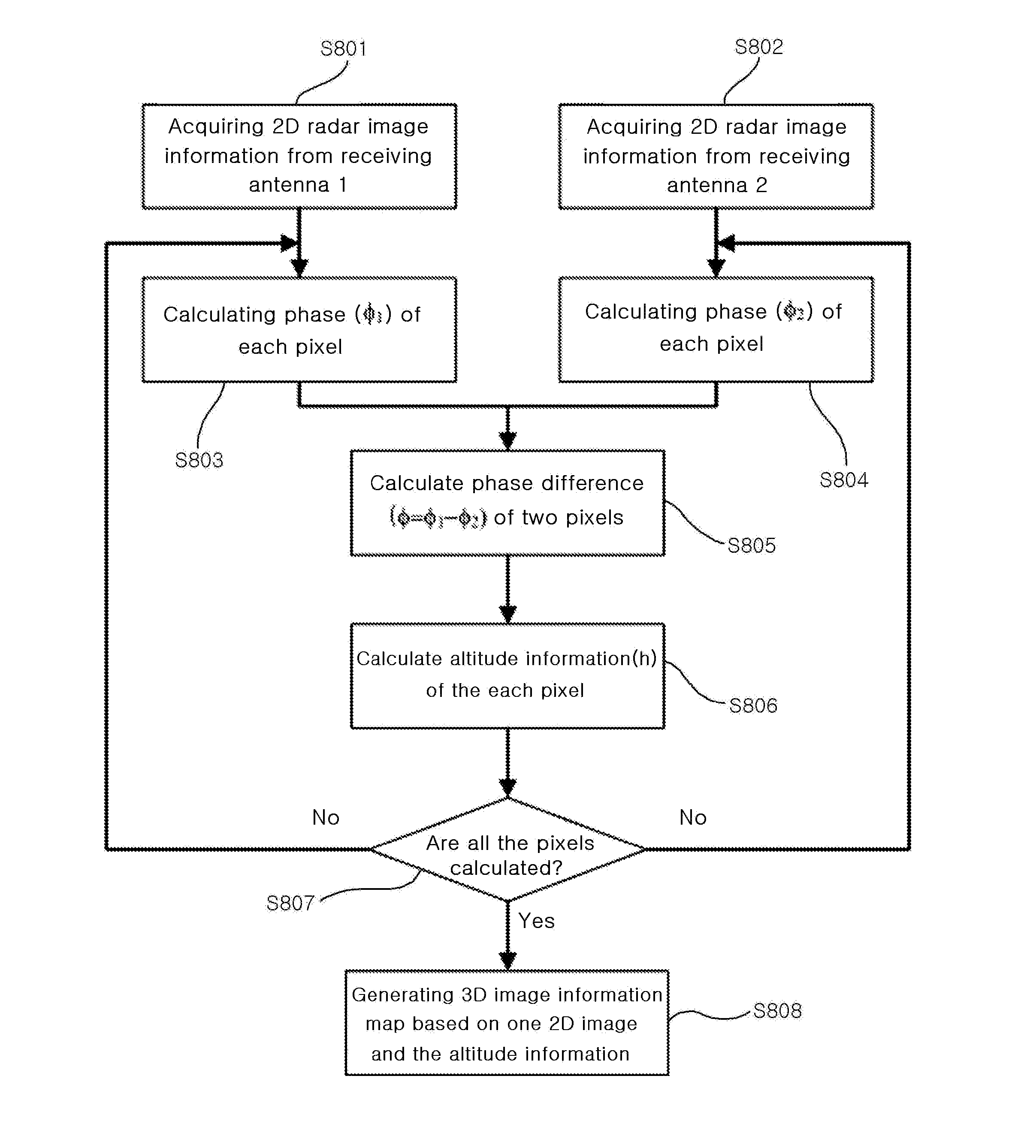
[0003]The present invention has been designed to solve the problems of prior arts, and aims to provide a forward-looking 3D imaging radar by which 3D image including altitude information at the front of the radar can be obtained, the difficulty in applying delay device on the receiver can be overcome by implementing independent receiver per receiving antenna, and radar image can be processed in real time, and a method for acquiring 3D image by using the radar.DISCLOSURE
[0018]By using the forward-looking 3D imaging radar of the present invention, it is possible to overcome the difficulty in applying delay device on the receiver by implementing independent receiver per receiving antenna, and the radar image can be processed in real time.

Problems solved by technology

Although the UWB (ultra-wide band) radar for foliage penetration aimed to process conventional 2D image has proposed a method for reducing the number of receiver by applying RF delay device to the receiver and receiving a signal with differentiated delay time per receiver, it was difficult to implement exact time delay for a short time by using the RF delay, making it hard to actual implementation of hardware.

Method used


Image

  • Forward-looking 3D imaging radar and method for acquiring 3D images using the same
  • Forward-looking 3D imaging radar and method for acquiring 3D images using the same
  • Forward-looking 3D imaging radar and method for acquiring 3D images using the same

Examples


Embodiment Construction

[0028]The invention will now be described with reference to the drawings attached.

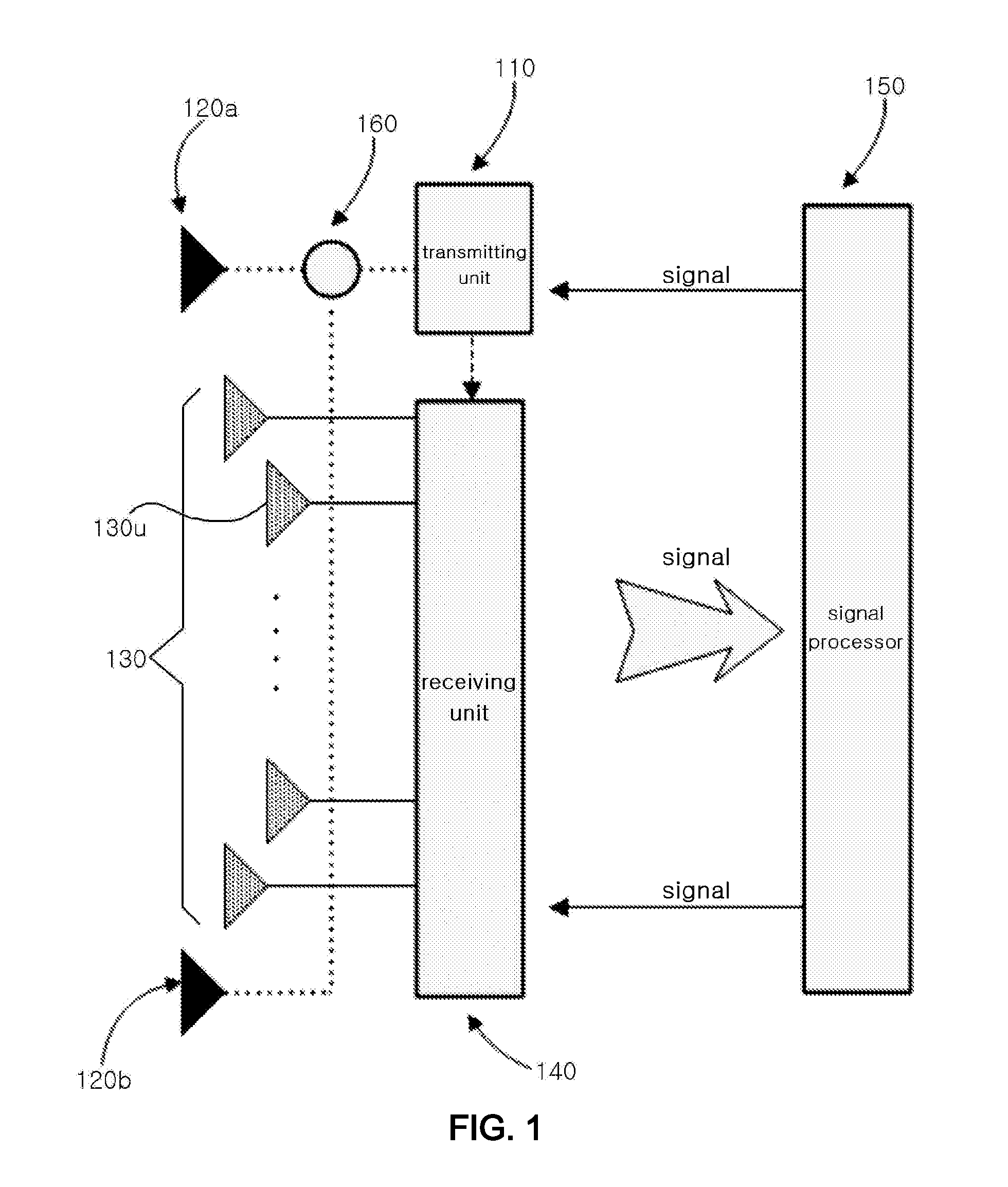
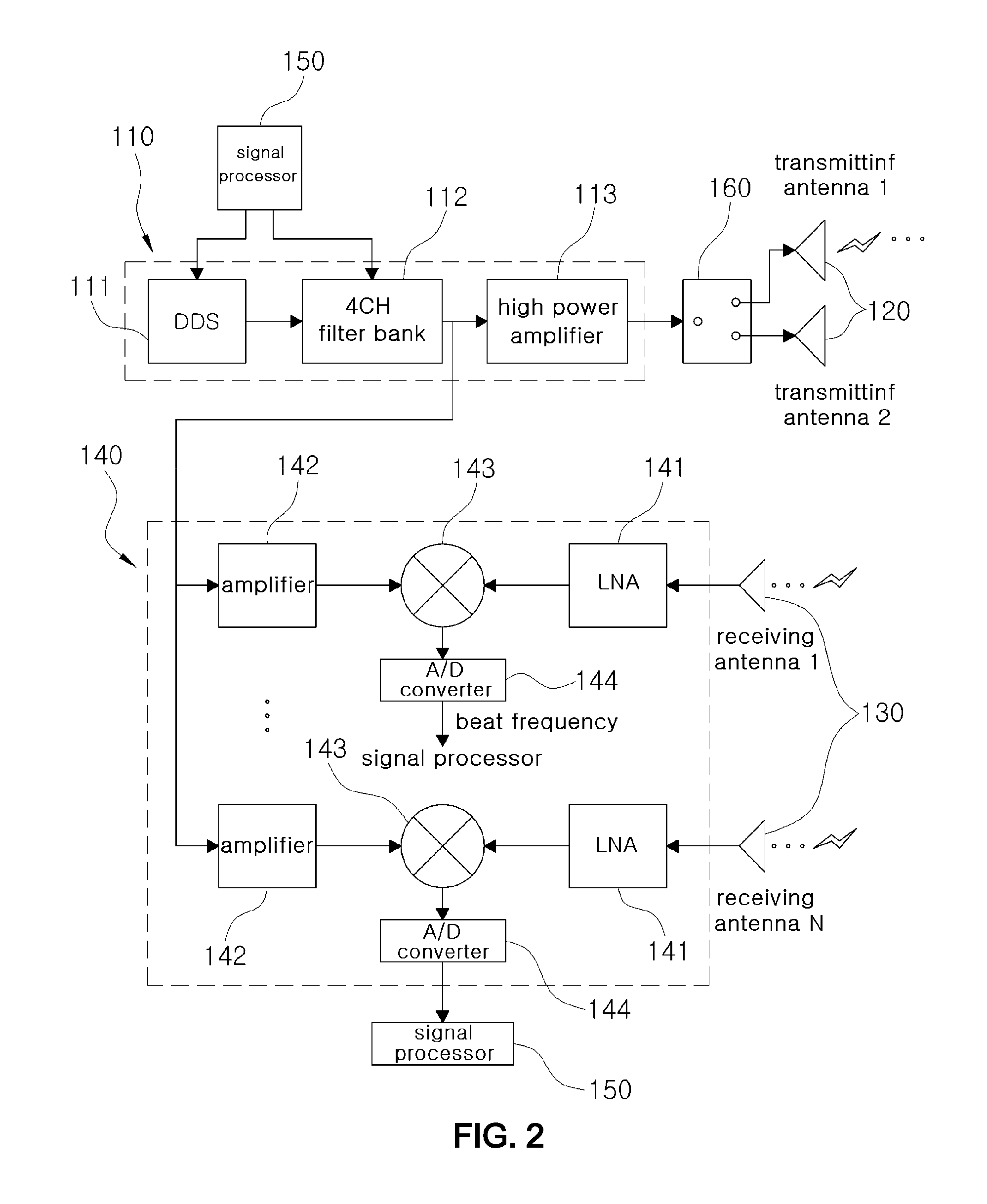
[0029]FIGS. 1 and 2 show the forward-looking 3D imaging radar of the present invention, FIG. 1 shows schematically the overall architecture of the forward-looking 3D imaging radar of the present invention, and FIG. 2 is the structure of the transmitting unit and receiving unit of the forward-looking 3D imaging radar of the present invention.

[0030]Referring to FIGS. 1 and 2, the forward-looking 3D imaging radar of the present invention comprises a transmitting unit 110, transmitting antennas 120a, 120b, a receiving antenna 130, a receiving unit 140, a signal processor 150.

[0031]The transmitting unit 110 generates RF signals to be radiated for observing object in front of the radar.

[0032]The transmitting antennas 120a, 120b radiate the RF signal generated by the transmitting unit 110 to the outside.

[0033]The receiving antennas 130 receive signals radiated from the transmitting antenna 120 and reflected b...


PUM


Abstract

Disclosure is a forward-looking 3D imaging radar, comprising: a transmitting unit which generates RF signals to be radiated for observing object in front of the radar; a transmitting antenna which radiates the RF signal generated by the transmitting unit; a receiving antenna which receives signals radiated from the transmitting antenna and reflected by the object in front of the radar; a receiving unit which mixes the signal received by the receiving antenna and the branched signal from the transmitting unit, and converts the signal to digital signal; and a signal processor which controls the operations of the transmitting unit and receiving unit, sends command to the transmitting unit to generate RF signals, receives the digitally converted signal from the receiving unit and extracts phase information of the object in front of the radar, and generates 3D radar image by producing altitude information based on the principle of interferometer.

Description

TECHNICAL FIELD[0001]The present invention relates to a forward-looking 3D imaging radar, and more particularly, to a forward-looking 3D imaging radar by which 3D image including altitude information at the front of the radar can be obtained, the difficulty in applying delay device on the receiver can be overcome by implementing independent receiver per receiving antenna, and radar image is processed in real time. The invention also relates to a method for acquiring 3D image by using the radar.BACKGROUND ART[0002]The research on the imaging radar device for an unmanned ground vehicle operating in the field has been published in the US Army Research Laboratory as an essay. But the research was on 2D imaging radar that did not include information on altitude. Although the UWB (ultra-wide band) radar for foliage penetration aimed to process conventional 2D image has proposed a method for reducing the number of receiver by applying RF delay device to the receiver and receiving a signal ...

Claims


Application Information

Patent Timeline
Patent Type & Authority Applications(United States)
IPC IPC(8): G01S13/08G01S13/00
CPCG01S13/36G01S13/89G01S13/87
Inventor SUN, SUN GUPARK, GYU CHURLCHO, BYUNG LAEHA, JONG SOO
Owner AGENCY FOR DEFENSE DEV
Learn More