Phase-type diffraction device, manufacturing method thereof and image pick-up apparatus

Inactive Publication Date: 2011-11-24
TOPPAN PRINTING CO LTD
View PDF11 Cites 3 Cited by
  • Summary
  • Abstract
  • Description
  • Claims
  • Application Information

AI Technical Summary

Benefits of technology

[0011]Objects of the present invention are to overcome the aforementioned problems and to provide a phase-type diffraction device of high quality and to provide a method of easily and stably manufacturi

Problems solved by technology

Because of these processes, the conventional optical low pass filter is accompanied with the drawbacks that considerable time and labor are required for the manufacture thereof.
However, it is difficult to uniformly orientate the mesogens in an inclined angle from the normal direction, especially at an angle of 20 to 70 degrees.
The phase-type diffraction grating utilizing the recessed/projected pattern is accompa

Method used


Image

  • Phase-type diffraction device, manufacturing method thereof and image pick-up apparatus
  • Phase-type diffraction device, manufacturing method thereof and image pick-up apparatus
  • Phase-type diffraction device, manufacturing method thereof and image pick-up apparatus

Examples


Embodiment Construction

[0024]Next, various aspects of the present invention will be explained in detail with reference to the drawings. Incidentally, constituent components exhibiting the same or a similar function are identified by the same reference number throughout all of the drawings, thereby omitting a duplicated explanation thereof.

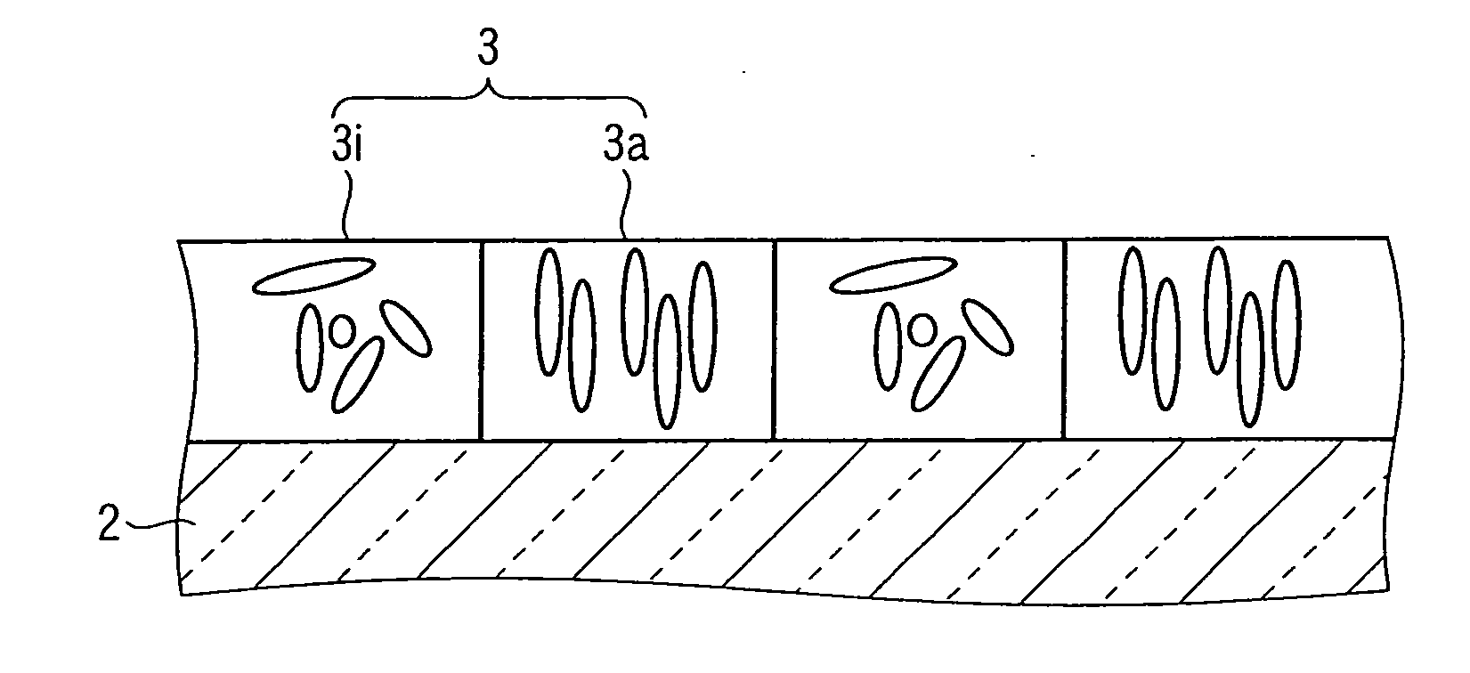
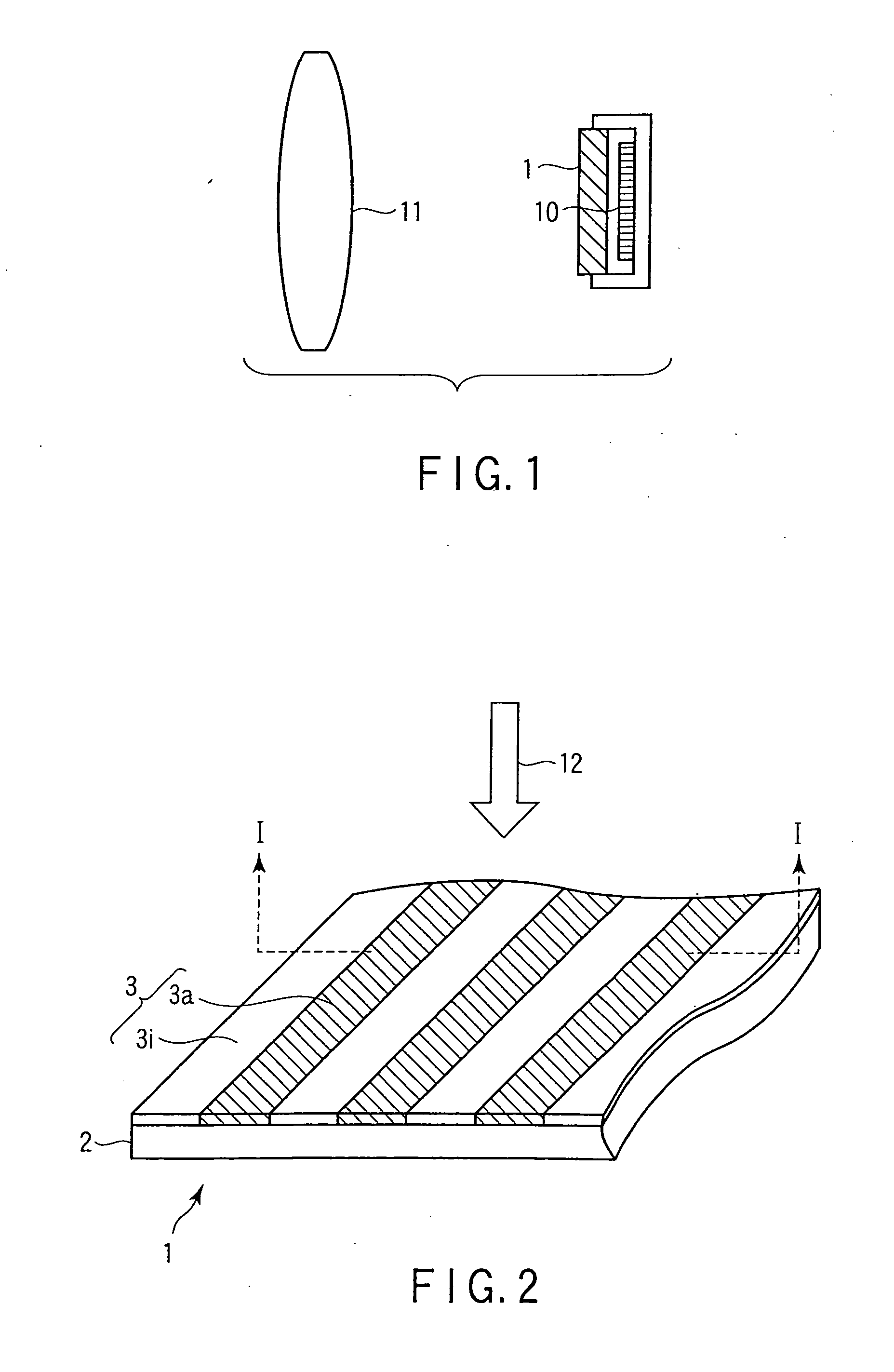
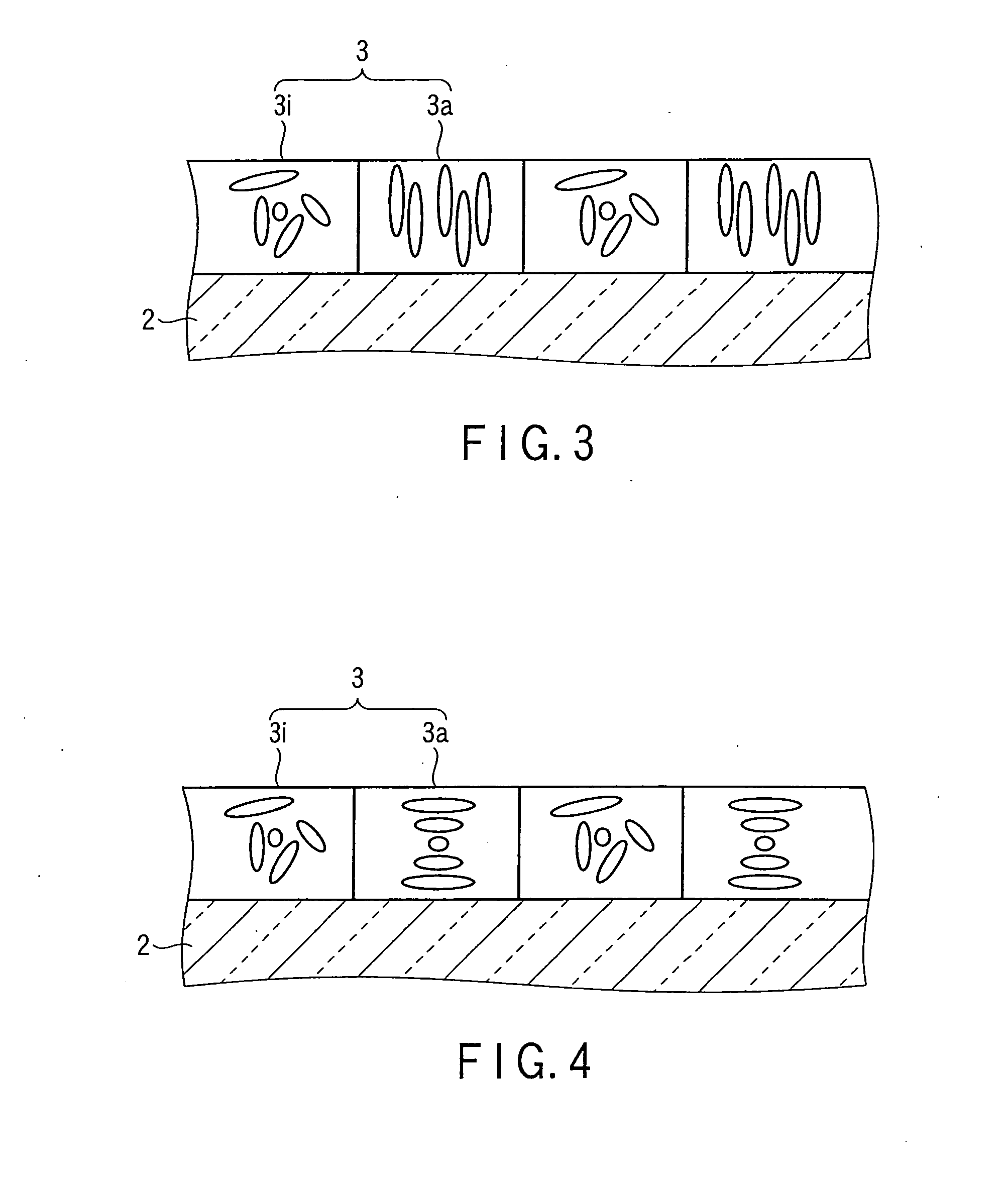
[0025]FIG. 1 is a diagram schematically illustrating the optical system of an image pick-up apparatus according to one aspect of the present invention. This optical system is constructed such that a diffraction device 1 is interposed between the image pick-up device 10 having a large number of light-receptive pixels arranged periodically thereon and an image pick-up lens 11. This diffraction device 1 is constituted at least by a solidified liquid crystal layer acting as a diffraction grating, and a transparent substrate supporting this solidified liquid crystal layer. As long as it is possible to enable this diffraction device 1 to exhibit desired properties as a low pas...


PUM


Abstract

A phase-type diffraction device is provided, which includes a transparent substrate having a front surface and a rear surface, and a solidified liquid crystal layer formed on the front surface of the transparent substrate and constituted by a continuous film includes at least a liquid crystal compound. The solidified liquid crystal layer is constituted by first and second regions arranged periodically. The first region is optically anisotropic and the second region is optically isotropic. The first region differs in in-plane average refractive index from the second region.

Description

CROSS-REFERENCE TO RELATED APPLICATIONS[0001]This application is a Continuation Application of PCT Application No. PCT / JP2010 / 051429, filed Feb. 2, 2010 and based upon and claiming the benefit of priority from prior Japanese Patent Application No. 2009-022727, filed Feb. 3, 2009, the entire contents of all of which are incorporated herein by reference.BACKGROUND OF THE INVENTION[0002]1. Field of the Invention[0003]This invention relates to a phase-type diffraction device to be used as a low pass filter in an image pick-up device and the like wherein a large number of light-receptive pixels each formed, for example, of a charge-coupled device (CCD), a complementary metal oxide-semiconductor (CMOS) are periodically arranged, and also relates to the manufacturing method of the phase-type diffraction device. This invention also relates to an image pick-up apparatus employing the diffraction device.[0004]2. Description of the Related Art[0005]In an image pick-up optical system employing ...

Claims


Application Information

Patent Timeline
IPC IPC(8): G02F1/13G03F7/26G02B5/00G02B5/18G02B5/30G02B27/46H01L27/14
CPCG02B5/1833H04N5/2254G02B5/1857G02B5/18G02B5/30G02B27/46H01L27/14
Inventor AKAO, SOSUKEITOI, TAKESHI
Owner TOPPAN PRINTING CO LTD
Why Eureka
Try Eureka