Manufacturing method for a glass roll and manufacturing apparatus for a glass roll

a manufacturing method and glass roll technology, applied in the direction of glass tempering apparatus, furnaces, charge manipulation, etc., can solve the problems of unrolled glass film accumulating distortion, unrolled glass film proportions that cannot be brought into close contact with each other, and unable to achieve weaving, etc., to achieve easy and stably manufacture glass rolls, and appropriate tensile for

Active Publication Date: 2017-06-13
NIPPON ELECTRIC GLASS CO LTD
View PDF27 Cites 3 Cited by
  • Summary
  • Abstract
  • Description
  • Claims
  • Application Information

AI Technical Summary

Benefits of technology

[0030]As described above, according to the present invention, it is possible to impart an appropriate tensile force to the elongated glass film that is rolled into the roll shape on the downstream side of the forming device without adversely affecting the accuracy of forming the glass film. Thus, it is possible to easily and stably manufacture the glass roll having a low risk of weaving.

Problems solved by technology

By the way, when the glass film is sequentially rolled into a roll shape under a state in which a tensile force is not sufficiently imparted to the glass film, portions of the rolled glass film cannot be brought into close contact with each other, and so-called weaving is likely to occur due to an effect of, for example, vibrations to be applied during transportation.
Therefore, when such a glass roll is introduced into various processing devices in the roll-to-roll system, distortion is accumulated in the unrolled glass film because various members constituting the processing devices are positionally fixed.
Such accumulation of the distortion may increase a risk of damage to the glass film.

Method used


Image

  • Manufacturing method for a glass roll and manufacturing apparatus for a glass roll
  • Manufacturing method for a glass roll and manufacturing apparatus for a glass roll
  • Manufacturing method for a glass roll and manufacturing apparatus for a glass roll

Examples


example

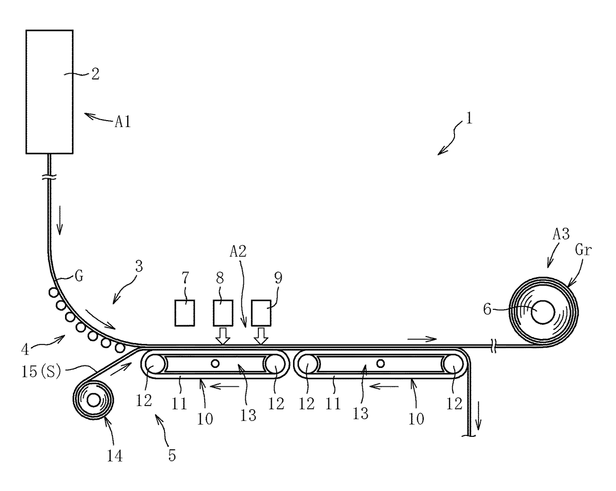
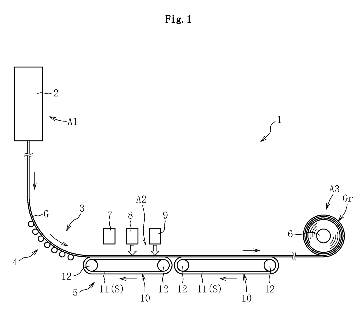
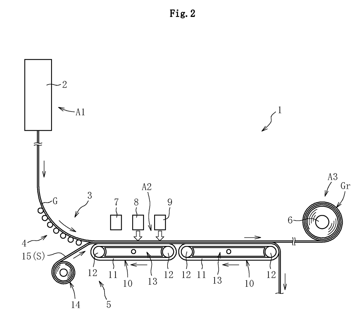
[0058]A confirmatory test was conducted to demonstrate usefulness of the present invention. In this confirmatory test, the manufacturing apparatus 1 having the structure illustrated in FIG. 1 was used, and glass films G having thicknesses of 100 μm and 50 μm were successively formed by the forming device 2 and continuously delivered to the downstream side by the horizontal conveyance section 5. Further, the glass films G were rolled by the rolling device 6. Under the condition described above, confirmation was made on the degree of the tensile force imparted to the glass film G interposed between the horizontal conveyance section 5 and the rolling device 6, and on the frequency of weaving occurring in the glass roll Gr, in accordance with the type of the endless belt 11 used as the support section S. In the confirmatory test, there were prepared five types of endless belts 11 having coefficients of static friction on the glass film G of 0.2, 0.6, 1.0, 1.6, and 3.2, and the frequency...


PUM

PropertyMeasurementUnit
thicknessaaaaaaaaaa
thicknessaaaaaaaaaa
thicknessaaaaaaaaaa

Abstract

A manufacturing method for a glass roll includes drawing a glass film downward vertically from a forming device, converting a delivery direction of the glass film from a vertical direction to a horizontal direction, continuously delivering the glass film to a downstream side by a horizontal conveyance section, and rolling the glass film into a roll shape on a downstream side of the horizontal conveyance section. While the glass film is supported in surface contact by an endless belt serving as a support section, which is provided in the horizontal conveyance section, a rolling force equal to or less than a static friction force, which is generated by a self-weight of the glass film between the glass film and the endless belt, is imparted to the glass film.

Description

TECHNICAL FIELD[0001]The present invention relates to an improvement of a technology for manufacturing a glass roll.BACKGROUND ART[0002]In recent years, a CRT display as an image display device has been gradually replaced by a flat panel display (FPD), which is lighter and thinner than the CRT display, such as a liquid crystal display (LCD), a plasma display (PDP), or an organic light-emitting diode (OLED) display. Further lightening of any such FPD is being promoted, and hence there arises a need for further thinning a glass substrate corresponding to one of the main components of the FPD.[0003]Further, for example, there is a growing use of an organic light-emitting diode not only for applications to a display that uses TFTs to blink light of three primary colors, but also as a plane light source, such as a backlight of the LCD and a light source for interior illumination, which emits only monochrome (for example, white) light. An illumination device that uses the organic light-em...

Claims


Application Information

Patent Timeline
Patent Type & Authority Patents(United States)
IPC IPC(8): B65G49/06C03B35/14B65H23/195C03B17/06
CPCB65H23/195B65G49/06C03B17/06B65H2801/61B65H18/22C03B35/00
Inventor MORI, KOICHINAKABAYASHI, AKIO
Owner NIPPON ELECTRIC GLASS CO LTD
Why Eureka
Try Eureka