Apparatus for lifting a group of containers or the like

Active Publication Date: 2011-11-24
MSK VERPACKUNGS SYST GMBH
View PDF6 Cites 10 Cited by
  • Summary
  • Abstract
  • Description
  • Claims
  • Application Information

AI Technical Summary

Benefits of technology

[0006]It is the object of the invention to avoid the afore-mentioned disadvantages and to specify an apparatus that makes it possible, with a small space requirement, to move the individually packaged goods, such as containers or cans, for example, from the lift table and the accumu

Problems solved by technology

By means of the clearance, which is given and created on the side of the base that faces the transport surface between the bottoms of the containers of the ro

Method used


Image

  • Apparatus for lifting a group of containers or the like
  • Apparatus for lifting a group of containers or the like
  • Apparatus for lifting a group of containers or the like

Examples


Embodiment Construction

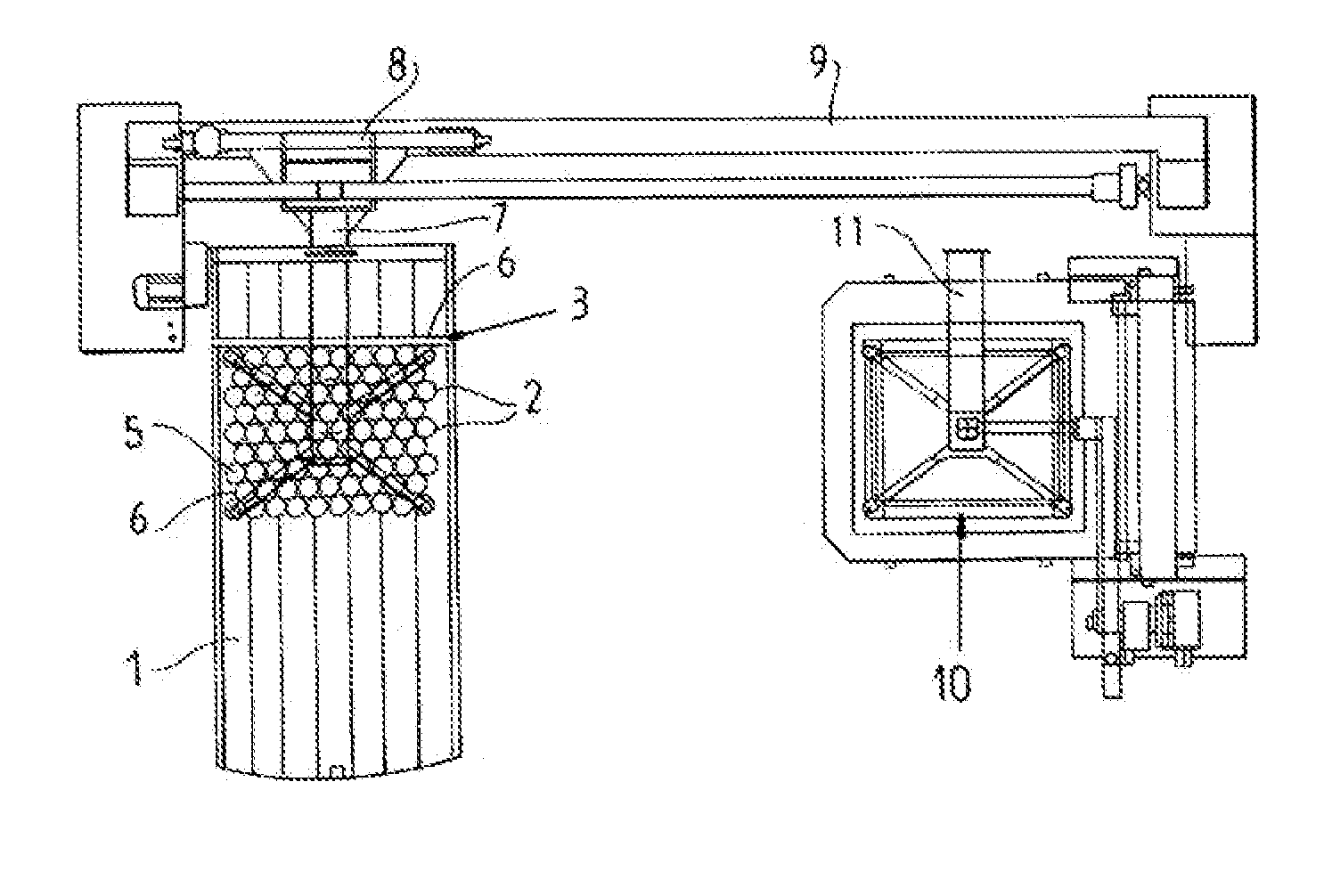
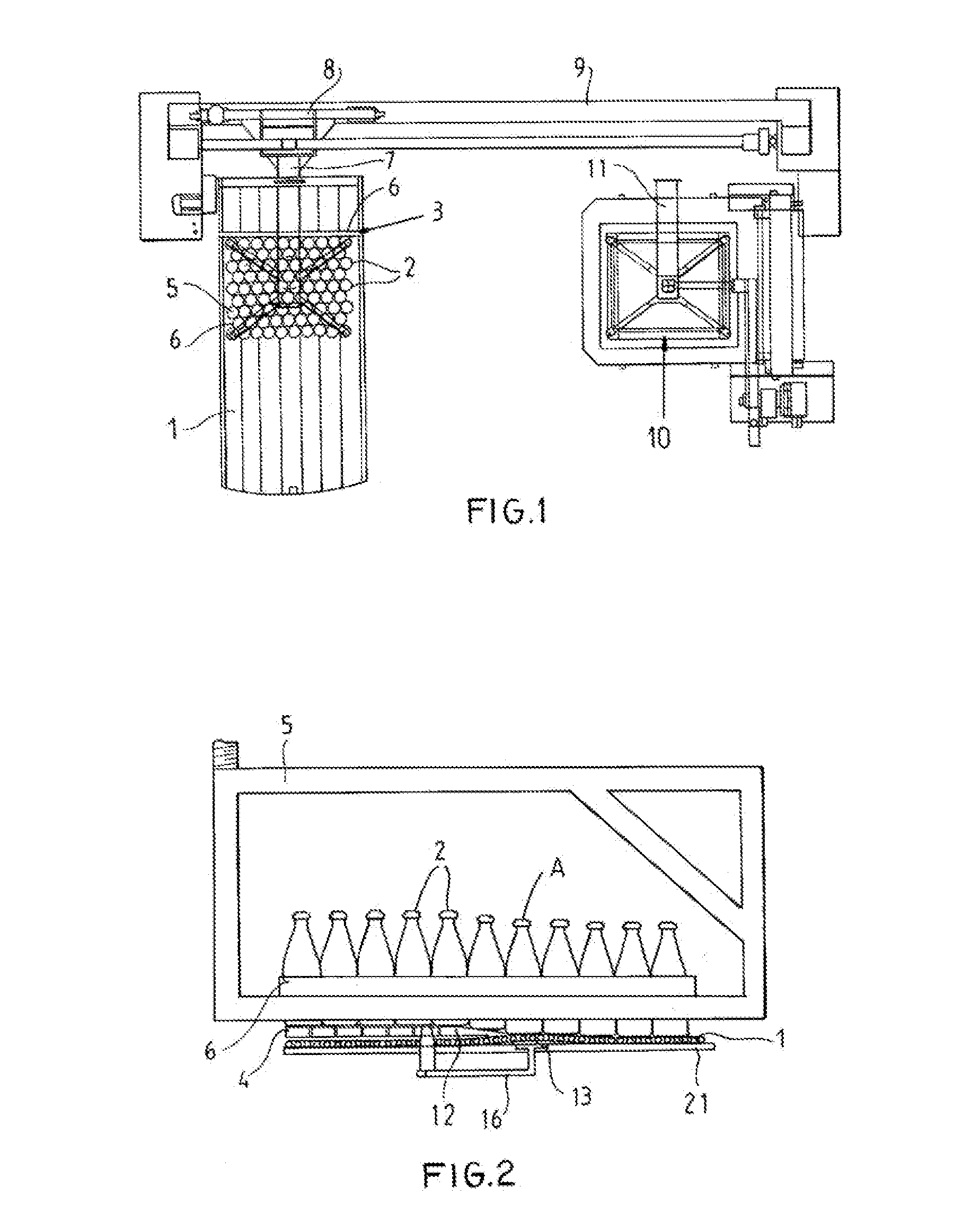
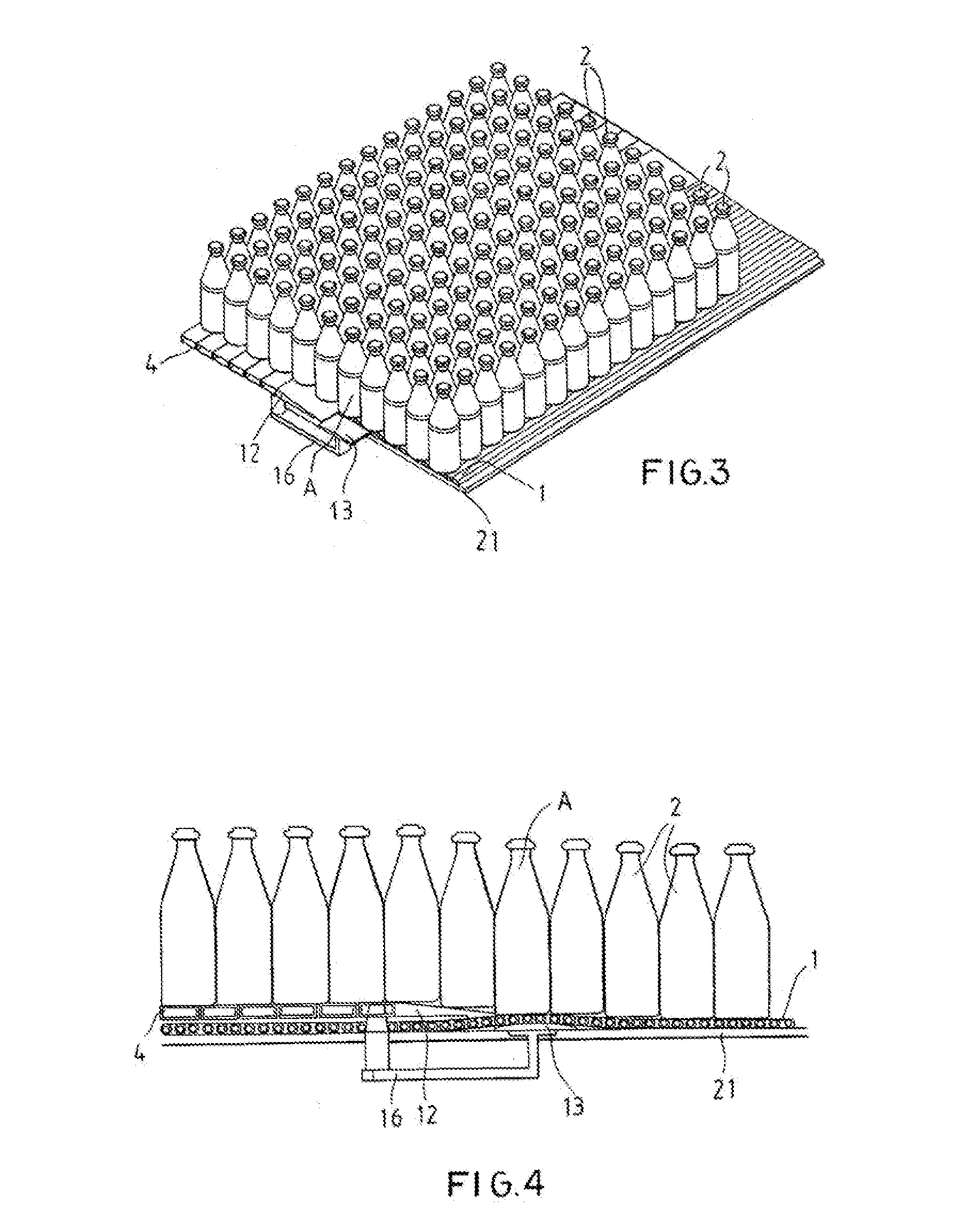
[0039]FIG. 1 is a top view of a palletizer. A conveyor belt forming a support 1 is located in the left-hand part of FIG. 1. As in FIGS. 2 to 21, the conveyor belt 1 moves continuously and is deflected between two unillustrated deflection rollers. At the same time, the part of the conveyor belt 1 illustrated in FIG. 1 forms the accumulating area. A group of containers 2 is stacked up in front of an unillustrated stop in the accumulating area.

[0040]Furthermore, a lifter 3 has a transport surface 4 that can be moved parallel to the base 1 and is formed from an array of parallel hinged-together slats as a blind having a frame 5. In the illustrated embodiment, the frame 5 has four flanges 6 that can be moved to gather the containers 2 into a centered group.

[0041]The lifter 3 is secured to a carriage 8 by a support structure 7. The support structure 7 permits vertical movement of the lifter 3. For horizontal displacement, the carriage 8 can ride along a guide rail 9. The deposition area i...


PUM


Abstract

An array of objects stands on a flexible web on a horizontal support, and a frame at the accumulation region gathers the objects at the downstream end into a group having a plurality of transverse rows. A transport element formed as a blind has an end edge and is shifted shiftable atop the web upstream in the direction between a ready position with the end edge spaced from the group standing on the web and a pickup position underlying the entire group. A lifting element underneath the web moves jointly with the transport element such that the web is raised immediately upstream of the end edge of the transport element to raise downstream edges of the objects and the transport element is engageable between the objects in the group and the web so the transport element can slide underneath the objects in the group.

Description

CROSS REFERENCE TO RELATED APPLICATIONS[0001]This application is a division of copending U.S. patent application Ser. No. 11 / 906,320 filed 1 Oct. 2007 with a claim to the priority of German patent application 10 2006 015 281 filed 4 Oct. 2006.FIELD OF THE INVENTION[0002]The invention relates to an apparatus for lifting a group of containers or the like, in particular consisting of a plurality of rows of containers or the like that are preferable arranged in parallel next to one another, comprising a base and a lifter, wherein the lifter has a transport surface that is formed in particular as a blind that can be displaced parallel to the base and preferable also comprising a frame that is embodied in is such a manner that the frame can be wrapped around by being slipped around the group of containers or by feeding the containers into the frame, wherein, prior to the lifting of the group of containers, the lifter is moved toward the group of containers in such a manner that the transp...

Claims


Application Information

Patent Timeline
IPC IPC(8): B65G47/00B65G47/90B65G47/28
CPCB65G47/66B65G2201/0244B65G57/24B65G57/06B65G57/16B65G57/18B65G60/00
Inventor MICHELS, FRANK
Owner MSK VERPACKUNGS SYST GMBH
Why Eureka
Try Eureka