Component feeding device

a technology of feeding device and component, which is applied in the direction of thin material handling, article separation, de-stacking articles, etc., can solve problems such as operator errors

Inactive Publication Date: 2011-11-24
HONG FU JIN PRECISION IND (SHENZHEN) CO LTD +1
View PDF16 Cites 8 Cited by
  • Summary
  • Abstract
  • Description
  • Claims
  • Application Information

AI Technical Summary

Problems solved by technology

However, the operator needs to repeat above-described process many times, which is fatiguing, and can cause operator errors.

Method used


Image

  • Component feeding device
  • Component feeding device
  • Component feeding device

Examples


Embodiment Construction

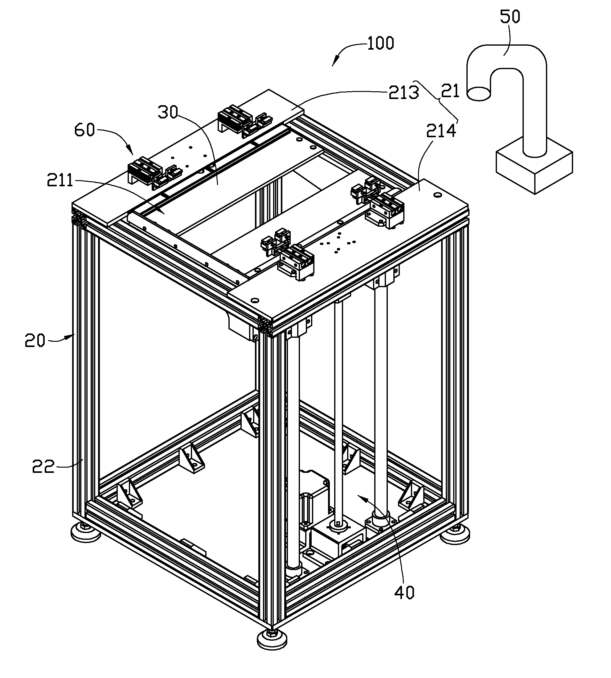
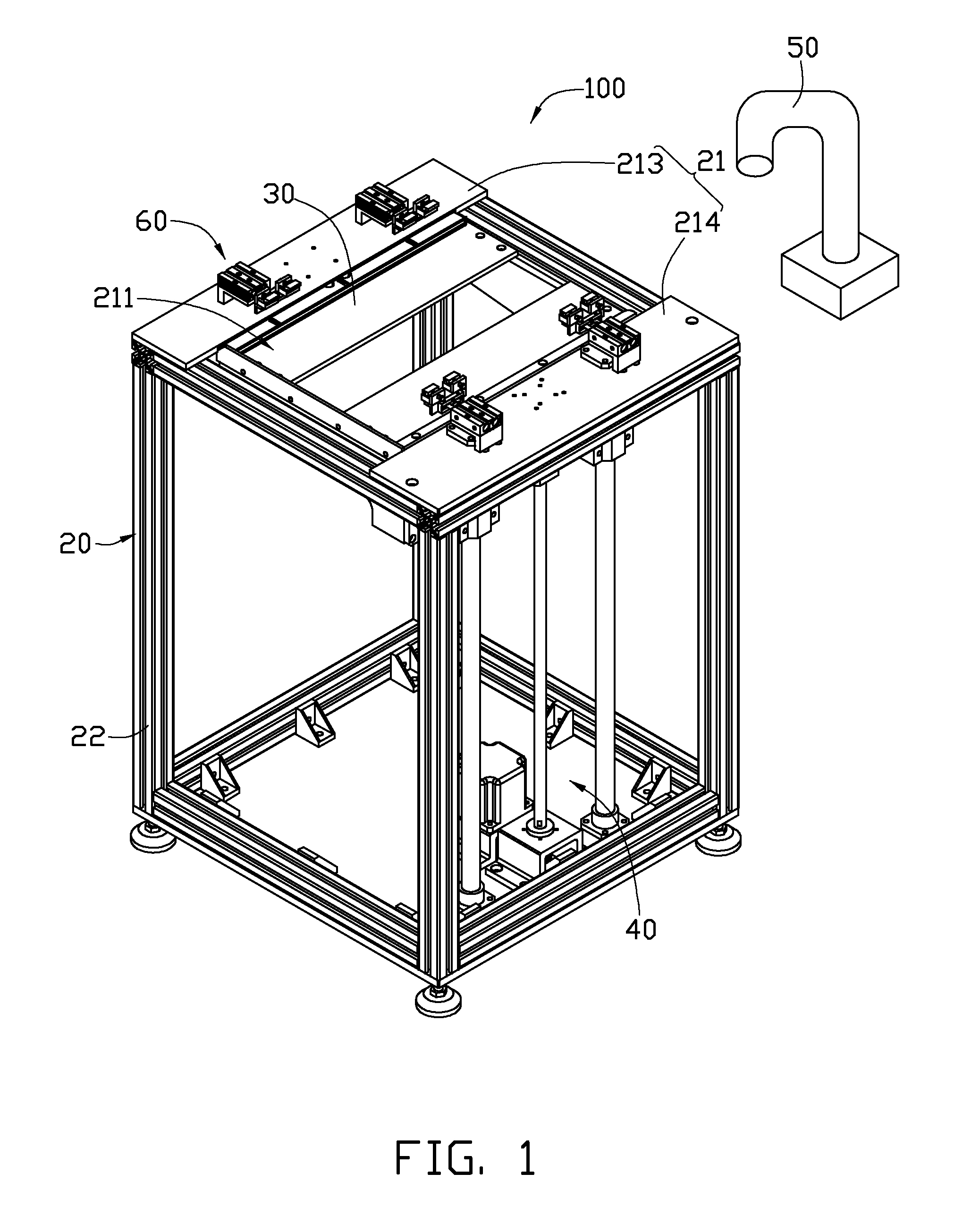
[0012]Referring to FIGS. 1 through 3, a feeding device 100 for separating a plurality of feed trays 200 vertically stacked together is shown. The feeding device 100 includes a support mechanism 20, a movable platform 30, a driving mechanism 40, a clutching mechanism 50, and a plurality of holding mechanisms 60.

[0013]The movable platform 30 is used to support the feed trays 200 including a first feed tray 201, a second feed tray 202 and so on (see FIG. 2). The holding mechanisms 60 are fixed on the support mechanism 20. The movable platform 30 can move from a first position to a second position. When the holding mechanisms 60 are in the first position, the holding mechanisms 60 grasps the second feed tray 202 adjacent to the first feed tray 201 on the top, so that the clutching mechanism 50 can detach the first feed tray 201 from the second feed tray 202. When the holding mechanisms 60 are in the second position, the holding mechanisms 60 are separated from the feed trays 200, and th...


PUM


Abstract

A feeding device includes a support mechanism, a movable platform, a driving mechanism mechanism, a clutching mechanism, and two or more holding mechanisms. The movable platform is movably connected to the support mechanism, and loads feed trays stacked together. The driving mechanism drives the movable platform to move relative to the support mechanism. The holding mechanisms are fixed on the support mechanism, and switch from a first position to a second position. When the holding mechanisms are positioned in the first position, the holding mechanisms grasp one feed tray adjacent to a feed tray at a top of the feed trays, and the clutching mechanism clutches the feed tray at the top of the feed trays. When the holding mechanisms are positioned in the second position, the holding mechanisms separate from the feed trays.

Description

BACKGROUND[0001]1. Technical Field[0002]The present disclosure relates to feeding devices and, more particularly, to a feeding device for separating a plurality of feed trays that are stacked together.[0003]2. Description of Related Art[0004]In an automatic production line, feed trays are generally used to receive components. Before feeding the components in the feed trays, the feed trays are vertically stacked together. When a suction cup is used to clutch a single tray, it may easily clutch several trays stacked together. Therefore, stacked feed trays should be manually separated. An operator may first carry a stack of feed trays to a work table of the automatic production line, and separate the feed trays one by one. The operator can then place the components in each feed tray. However, the operator needs to repeat above-described process many times, which is fatiguing, and can cause operator errors.[0005]Therefore, there is room for improvement within the art.BRIEF DESCRIPTION O...

Claims


Application Information

Patent Timeline
Patent Type & Authority Applications(United States)
IPC IPC(8): B65G59/02
CPCH05K13/0434B65G59/02
Inventor XU, XIAO-MINGSONG, JIN-JIN
Owner HONG FU JIN PRECISION IND (SHENZHEN) CO LTD
Why Eureka
Try Eureka