
Battery module

a battery module and battery technology, applied in the field of batteries, can solve the problems of deteriorating assembly quality, deformation of the unit battery, and the inability of the connection member and the tightening member to adapt to the irregular tolerance of the unit battery or the volume change, so as to reduce the time required for assembly, facilitate the assembly, and increase the assembly quality of the battery module

Inactive Publication Date: 2011-11-24
ROBERT BOSCH GMBH +1
View PDF4 Cites 50 Cited by
  • Summary
  • Abstract
  • Description
  • Claims
  • Application Information

AI Technical Summary

Benefits of technology

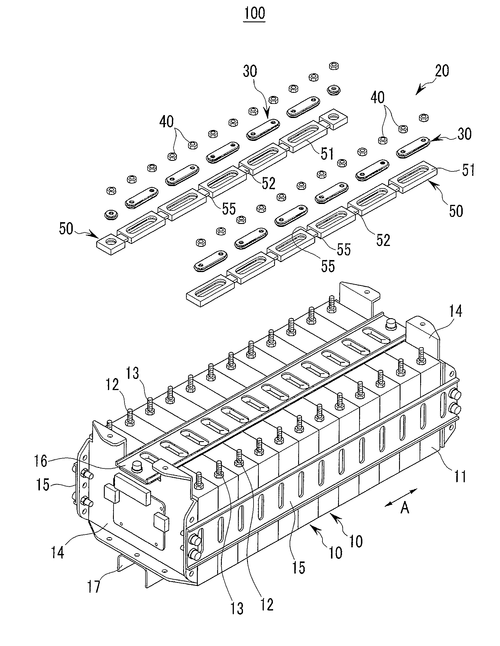
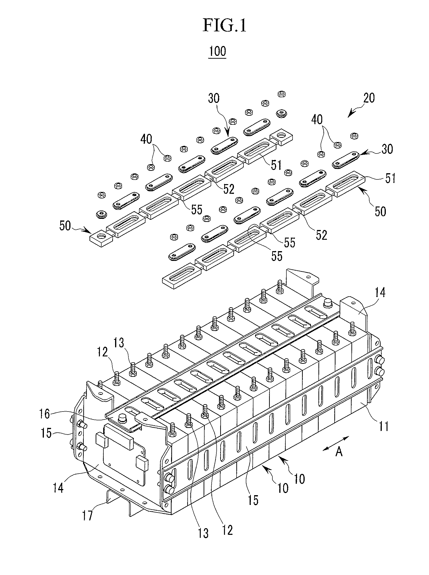
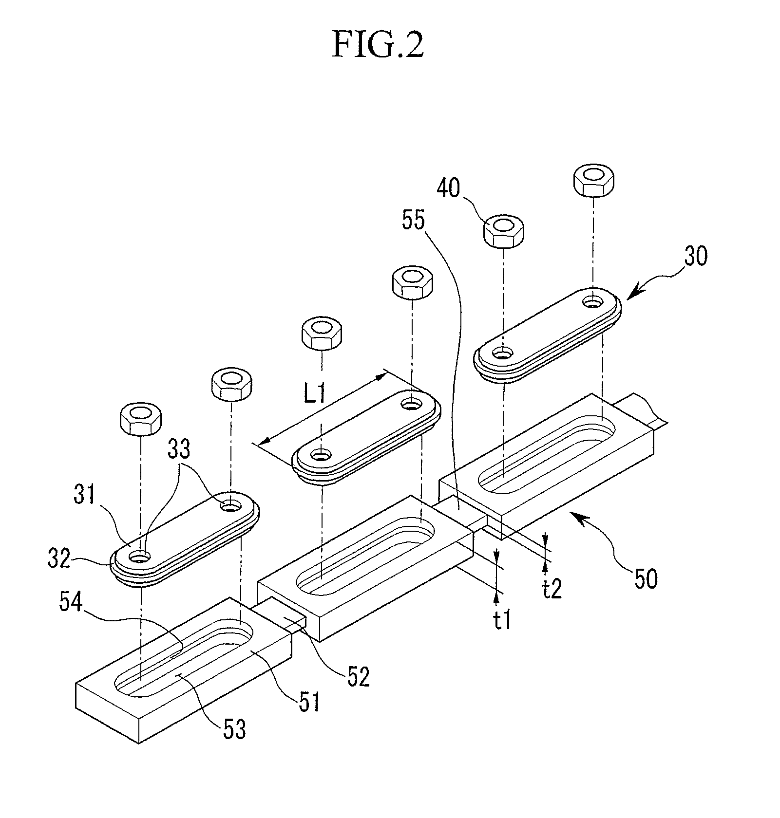
[0011]An aspect of an embodiment of the present invention is directed toward a battery module that is easily assembled by a plurality of improved bus bars. The battery module is capable of preventing deformation of a unit battery and increases the assembly quality of a connection member to accommodate a manufacturing tolerance of the unit battery and / or a volume change.
[0021]According to an exemplary embodiment of the present invention, the insulating guide is used to configure the plurality of bus bars in the correct position for assembly such that the assembly may be easy, and thereby the time required for the assembly may be reduced. Also, the insulating guide is made of the elastic insulating material such that the manufacturing tolerance and the volume change of the unit battery that is generated in the charging and discharging process of the unit battery may be easily accommodated. Accordingly, the assembled quality of the battery module may be increased, and the deformation of any of the unit batteries may be prevented.

Problems solved by technology

However, the connection member including the bus bar and the tightening member cannot be adapted for an irregular tolerance of the unit battery or the volume change.
This may lead to deterioration of the assembly quality and deformation of the unit battery.

Method used


Image

  • Battery module
  • Battery module
  • Battery module

Examples


Embodiment Construction

[0029]In the following detailed description, only certain exemplary embodiments of the present invention are shown and described, by way of illustration. As those skilled in the art would recognize, the invention may be embodied in many different forms and should not be construed as being limited to the embodiments set forth herein. Also, in the context of the present application, when a first element is described as being “coupled to” a second element, the first element may be directly coupled to the second element or may also be indirectly coupled to the second element with one or more intervening elements interposed there between. Further, some of the elements that are not essential to the complete understanding of the invention are omitted for clarity. Also, like reference numerals refer to like elements throughout the specification.

[0030]Hereinafter, embodiments of the present invention will be described in more detail with reference to FIGS. 1 to 6 so that those skilled in the...


PUM

PropertyMeasurementUnit
widthaaaaaaaaaa
elasticaaaaaaaaaa
bendingaaaaaaaaaa

Abstract

A battery module of the present invention includes a plurality of unit batteries and a connection member electrically connecting the plurality of unit batteries. The connection member includes: a plurality of bus bars, each of the plurality of bus bar having two through-holes respectively corresponding to two electrode terminals protruding from two adjacent unit batteries of the plurality of unit batteries; and an insulating guide having a plurality of holder units configured to support the plurality of bus bars, and a plurality of narrow width portions positioned between the plurality of holder units and connecting the plurality of holder units along a first direction.

Description

CROSS-REFERENCE TO RELATED APPLICATION[0001]This application claims priority to and the benefit of Korean Patent Application No. 10-2010-0048118, filed in the Korean Intellectual Property Office on May 24, 2010, the entire content of which is incorporated herein by reference.BACKGROUND[0002]1. Field[0003]The following description relates to a battery module including a plurality of unit batteries coupled by a connection member.[0004]2. Description of the Related Art[0005]A battery module is a module including a plurality of unit batteries connected in series, thereby realizing high power and a large capacity. A rechargeable battery module is used as a power supply for a device requiring a large capacity, such as for driving motors in electric vehicles or hybrid vehicles. The unit battery may be a rechargeable battery that is capable of being recharged. Recently, a high power rechargeable battery using a non-aqueous electrolyte with high energy density has been developed.[0006]A posi...

Claims


Application Information

Patent Timeline
Patent Type & Authority Applications(United States)
IPC IPC(8): H01M2/24H01M50/528H01M50/209H01M50/529H01M50/503H01M50/507H01M50/522H01M50/55H01M50/553H01M50/567
CPCH01M2/1077H01M2/305H01M2/206H01M2/202Y02E60/10Y02P70/50H01M50/553H01M50/507H01M50/55H01M50/567H01M50/209H01M50/522H01M50/503H01M50/528H01M10/02B60L50/50
Inventor KIM, TAE-YONG
Owner ROBERT BOSCH GMBH
Learn More