High conductivity energy-saving clamping device

a clamping device and high conductivity technology, applied in the direction of coupling device connection, electrical apparatus, connection, etc., can solve the problems of increased raw material loss, poor electric conduction, serious pollution of the environment during the manufacture, etc., and achieve the effect of improving conductivity and high conductivity energy saving

Active Publication Date: 2011-11-24
SHANGHAI GUANGWEI ELECTRIC & TOOLS +2
View PDF13 Cites 15 Cited by
  • Summary
  • Abstract
  • Description
  • Claims
  • Application Information

AI Technical Summary

Benefits of technology

[0008]The invention is to provide a high conductivity energy-saving clamping device by increasing its contact area with the external conductor to improve the conductivity.
[0022]The invention is superior to the known technology with the following advantages:
[0023]1. Saving material: the invention does not adopt the extensively used tooth-like conductive parts of known technology, so manufacture process is simplified and raw material & resources saved and cost economized. This is a contribution to the intensive enterprises and economy.
[0025]3. Environmental protection: the invention does not adopt the tooth-like conductive parts of known technology which are widely used nowadays. So electroplating process is avoided as it is only used for producing the tooth-like parts. This greatly decreases environmental pollution and conforms to the environmental philosophy of emission reduction and low carbon green economy.

Problems solved by technology

1. Environmental pollution: known clamps use tooth-like conductive parts to connect cables and external conductors. To be economical and artistic, the tooth-like parts are generally made of iron and reprocessed with copper coating and galvanization. Therefore, the environment is seriously polluted during the manufacture.
2. Increased raw material loss: the production of the known clamps, not only requires wire casing and metal wires, but also needs conductive material to produce the tooth-like conductive parts.
3. Poor electric conduction: using tooth-like parts to connect the external conductor, known clamps only have the tooth surface to establish connection, so this small contact area leads to poor electric conduction.
4. Complicated manufacture procedures: to produce known clamps, metal wires need to be connected with the tooth-like conductive parts. Moreover, the tooth-like parts ought to be made independently and then assembled into the whole clamping device. The manufacture procedures are loaded down with trivial details.

Method used


Image

  • High conductivity energy-saving clamping device
  • High conductivity energy-saving clamping device
  • High conductivity energy-saving clamping device

Examples


embodiment 1

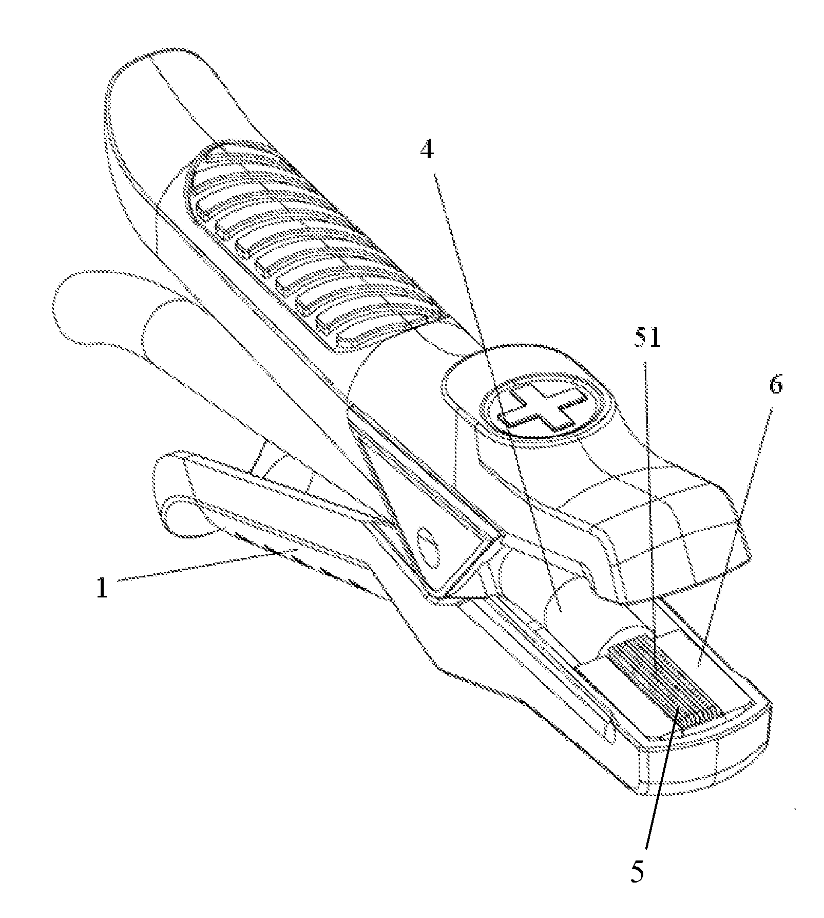
[0038]As shown in FIG. 3 and FIG. 4, conductive material 5 (usually copper or other metal wires) is plainly set on one part of the juncture at the mouth of clamp 1, and the front end of conductive material 5 is fixed between the mouth of clamp 1 and the insulation plate 6 (in this embodiment, insulation plate 6 is made of plastics). Conductive surface 51 is formed on the surface of the insulation plate 6. When connecting with clamp 1, we open it to expose the conductive surface 51. As clamp 1 connects an external conductor (a wiring terminal for instance), conductive surface 51 directly contacts the wiring terminal to effect electric conduction. Due to the effective increase in contact area, the conductivity performance of the clamping device in this invention is 10% to 15% higher than that of common clamps with known technology.

[0039]To better effect the Embodiment 1, we can place metallic members (not shown in the figures) to cover conductive surface 51 such that the members (usua...

embodiment 2

[0042]According to different forms of the external conductor, as shown in FIGS. 6 and 7, conductive material 5 goes through a through hole of the insulation plate 6 and extends from the top of the insulation plate 6 to form cluster-like conductive material 52. When using clamp 1 to connect, we open the head of clamp 1 to entirely expose the cluster-like conductive material 52. When clamp 1 connects an external conductor, such as a wiring terminal, cluster-like conductive material 52 contacts the wiring terminal, and electric conduction is achieved. Due to effectively increased contact area, the conductivity performance of the clamping device of this invention is 10% to 15% higher than that of common clamps of known technology.

[0043]As shown in FIG. 8, if conductive material 5 from the cable 4 is divided into two parts, and the two parts vertically extend from the two parts of the juncture at the mouth of clamp 1 respectively, two cluster-like conductive material 52 are thus formed t...

embodiment 3

[0044]According to the different forms of external conductor required by the clamp, as shown in FIG. 9, conductive material 5 from the cable 4 is divided into two parts. One part plainly set on one part of the juncture at the mouth of clamp 1 forms the conductive surface 51 and another part vertically extending from another part of the juncture at the mouth of clamp 1 forms cluster-like conductive material 52. When connecting with clamp 1, we open it to expose conductive surface 51 and cluster-like conductive material 52. As clamp 1 connects the external conductor (a wiring terminal for instance), conductive surface 51 and cluster-like conductive material 52 directly contact the wiring terminal to conduct electricity. Due to the effective increase in contact area, the conductivity performance of the clamping device in this invention is 10% to 15% higher than that of common clamps with known technology.

[0045]From the above mentioned embodiments, the invention has the following advant...


PUM


Abstract

The high conductivity energy-saving clamping device comprises a clamp and a cable fixed upon the clamp. Inside the cable, the conductive material protrudes and is set on the juncture of the clamp and the external conductor. When the clamp is connected to the external conductor, the conductive material and the external conductor contact and meet. This invention possesses the following advantages: it simplifies the production technology, lessens raw materials needed for production and hence saves resources and cost by the direct contact of the conductive material and the external conductor; moreover, due to the increase of conductive contact area, it enhances the electrical conductivity by 10% to 15% compared to those common clamps which use tooth-like conductive parts to connect the external conductor. Meanwhile, the invention greatly decreases environmental pollution by omitting the plating process of tooth-like conductive parts.

Description

FIELD OF TECHNOLOGY[0001]The invention involves a clamping device to effect conductive connection, and the clamping device is high conductivity energy-saving one using conductive material to directly contact an external conductor.BACKGROUND OF THE INVENTION[0002]Nowadays, it is common to use the clamp structure in FIG. 1 and FIG. 2 to effect the connection of electric conduction. FIG. 1 and FIG. 2 are drawings of the structure of a known clamp and the enlarged mouth thereof From the drawings, cable 4 goes through clamp 1; conductive material 5 from inside cable 4 is connected to the big tooth 2 set beneath the mouth of clamp 1. The small tooth 3 is set on the clamping region in the mouth of clamp 1. The two teeth meet together to connect the conductor of an external device. When using the clamping device, clamp 1 is opened to effect the connection of the big tooth 2 and the external conductor. Then cable 4 and the two teeth are connected to the external conductor, thereby effecting ...

Claims


Application Information

Patent Timeline
Patent Type & Authority Applications(United States)
IPC IPC(8): H01R4/48
CPCH01R13/025H01R11/24
Inventor FAN, YEPINGWU, YONGYAN, ZHANGXIYU, DIDUAN, WEI
Owner SHANGHAI GUANGWEI ELECTRIC & TOOLS
Why Eureka
Try Eureka