
Framework for a software error inject tool

a software error and injecting tool technology, applied in the field of framework for software error injecting tools, can solve problems such as difficulty in creating conditions to naturally exercise certain code paths, error code paths, and computerized systems to exhibit erroneous behavior, and achieve the effect of reducing the number of times code must be retrieved

Inactive Publication Date: 2011-11-24
IBM CORP
View PDF43 Cites 29 Cited by
  • Summary
  • Abstract
  • Description
  • Claims
  • Application Information

AI Technical Summary

Benefits of technology

[0086]FIG. 13 illustrates a computer architecture 1300 that may be used in accordance with certain embodiments. Computing device 100 and/or storage controller 140 may implement computer architecture 1300. The computer architecture 1300 is suitable for storing and/or executing program code and includes at least one processor 1302 coupled directly or indirectly to memory elements 1304 through a system

Problems solved by technology

For a complex and highly resilient computerized system (e.g., one in which a majority of the functions are implemented by computer programs), it may be difficult to create conditions to naturally exercise certain code paths, such as error code paths.
This creates challenges for software development and quality assurance.
An error inject may be described as execution of the error inject code or other method that can cause the computerized system to exhibit erroneous behavior.
So, the cost of repeating and / or running a series of different error injects may be high, especially for a large computerized system.
This is because it may take some time to recompile and restart such a large computerized system.
Also, for a complex error inject that involves multiple error inject points, the current conventional approach tends to make the error inject code so unique that it becomes hard to re-use the error inject code.
This makes it more difficult to iterate through different test scenarios in the test process.

Method used


Image

  • Framework for a software error inject tool
  • Framework for a software error inject tool
  • Framework for a software error inject tool

Examples


embodiment details

Additional Embodiment Details

[0077]As will be appreciated by one skilled in the art, aspects of the present invention may be embodied as a system, method or computer program product. Accordingly, aspects of the present invention may take the form of an entirely hardware embodiment, an entirely software embodiment (including firmware, resident software, micro-code, etc.) or an embodiment combining software and hardware aspects that may all generally be referred to herein as a “circuit,”“module” or “system.” Furthermore, aspects of the present invention may take the form of a computer program product embodied in one or more computer readable medium(s) having computer readable program code embodied thereon.

[0078]Any combination of one or more computer readable medium(s) may be utilized. The computer readable medium may be a computer readable signal medium or a computer readable storage medium. A computer readable storage medium may be, for example, but not limited to, an electronic, ma...


PUM


Abstract

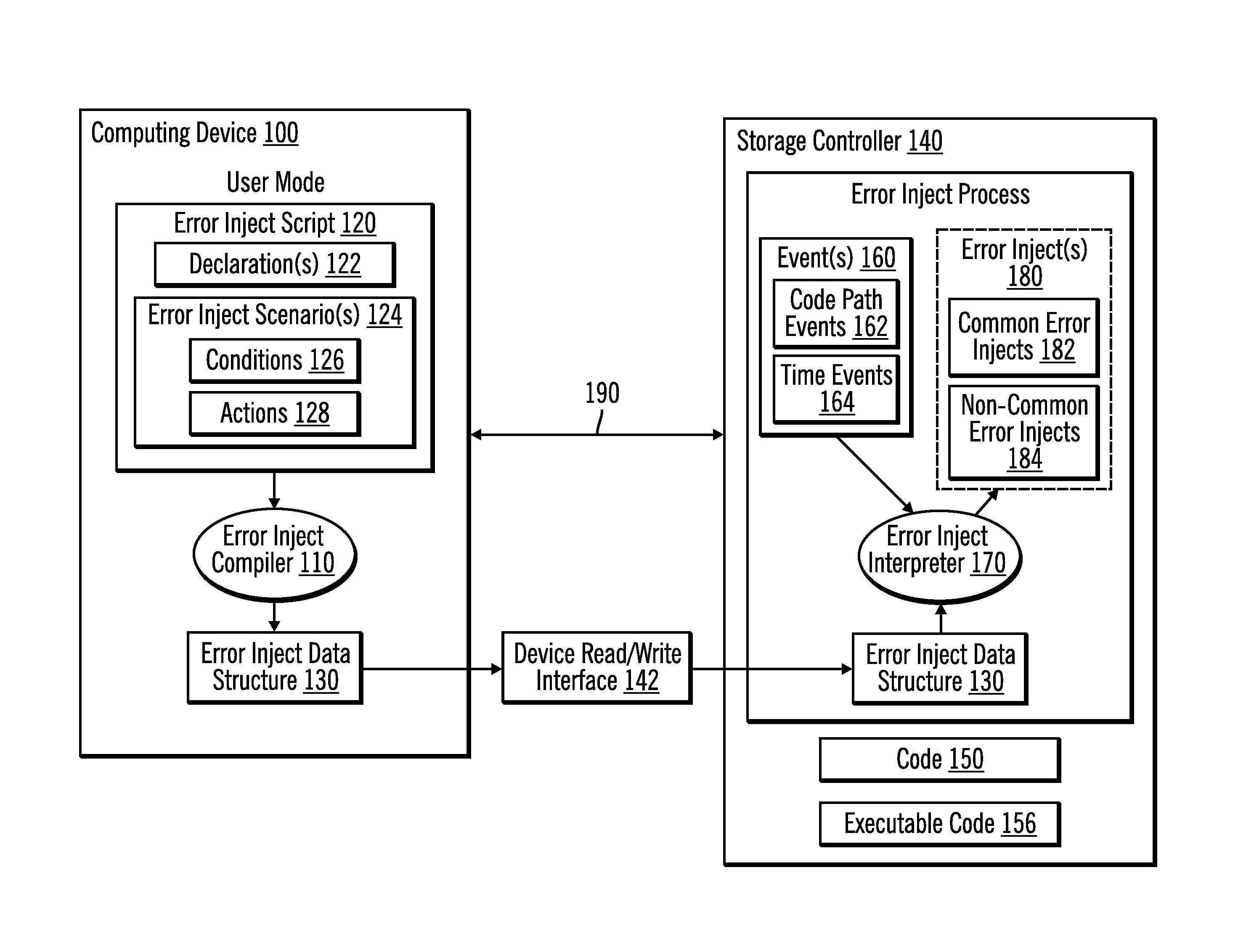
Provided are techniques for receiving an error inject script that describes one or more error inject scenarios that define under which conditions at least one error inject is to be executed and compiling the error inject script to output an error inject data structure. While executing code that includes the error inject, an indication that an event has been triggered is received, conditions defined in the one or more error inject scenarios are evaluated using the error inject data structure, and, for each of the conditions that evaluates to true, one or more actions defined in the error inject script for the condition are performed.

Description

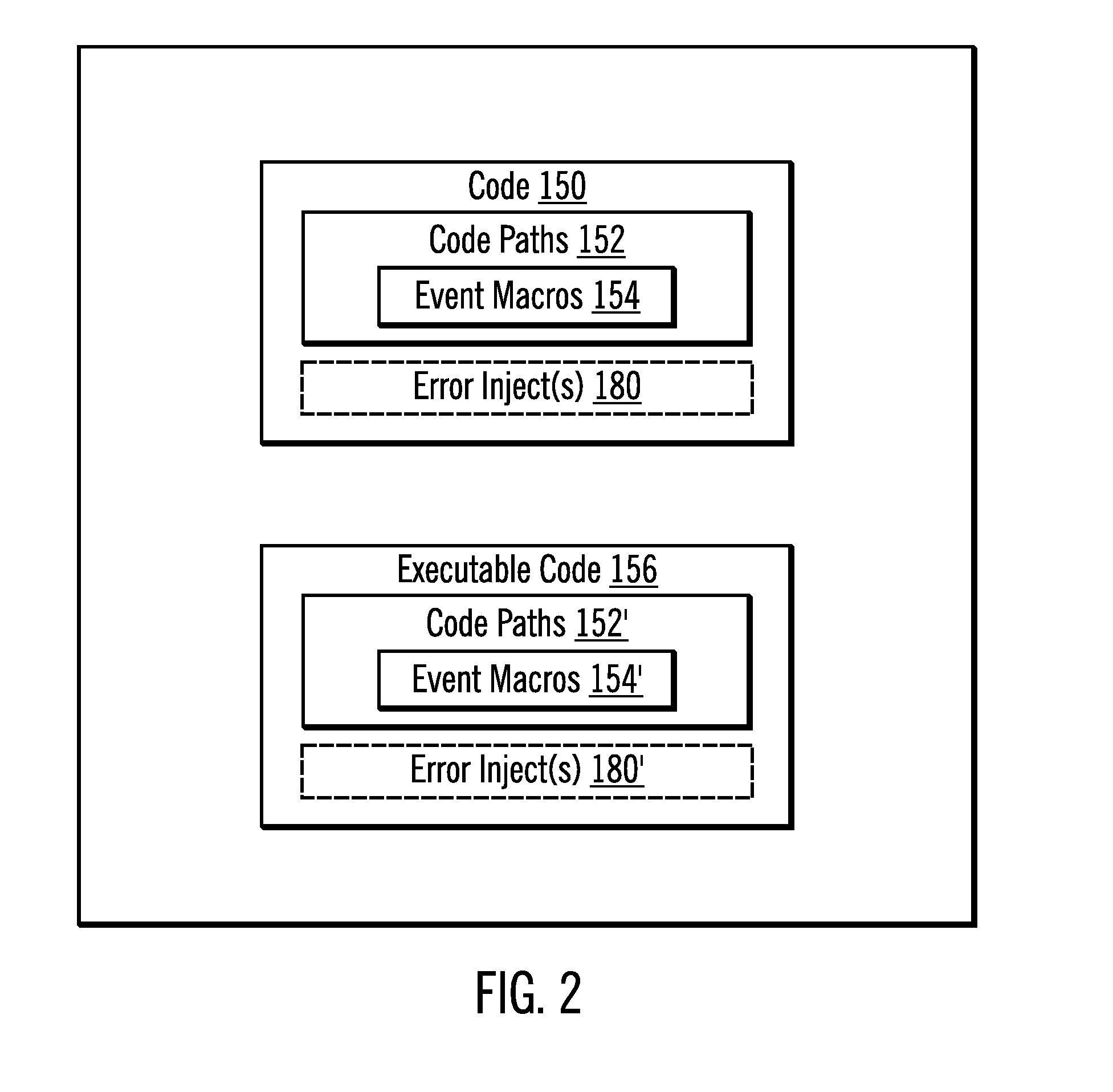
BACKGROUND[0001]1. Field[0002]Embodiments of the invention relate to a framework for a software error inject tool.[0003]2. Description of the Related Art[0004]For a complex and highly resilient computerized system (e.g., one in which a majority of the functions are implemented by computer programs), it may be difficult to create conditions to naturally exercise certain code paths, such as error code paths. This creates challenges for software development and quality assurance.[0005]A common conventional approach is to implement error inject code (including test scenario code and error injects) embedded within normal code (i.e., code that is compiled and executed). Error inject code may be described as one or more computer programs that add erroneous behavior to the normal program when they are executed. This is done to test possible error conditions. Then, depending on how safe the implementation is (i.e., how easily the error inject code could be incorrectly executed as part of the...

Claims


Application Information

Patent Timeline
IPC IPC(8): G06F9/44
CPCG06F11/3624G06F11/3696G06F11/3668G06F11/3636G06F11/3644G06F11/3466G06F8/41G06F11/3664
Inventor SONG, CHENG-CHUNG
Owner IBM CORP
Learn More