Stepped dimming device for LED lamp

Inactive Publication Date: 2011-12-01
MASS TECH (HK) LTD
View PDF3 Cites 42 Cited by
  • Summary
  • Abstract
  • Description
  • Claims
  • Application Information

AI Technical Summary

Benefits of technology

[0022]The microcontroller control circuit can detect the output signal from the switch signal detection circuit module or the analog signal from the external DC signal source. The output of the microcontroller is connected to the power output circuit of the switch power supply circuit module. When a dimming signal is identified, the output of the microcontroller control circuit can adjust the magnitude of the current which flows from the power output circuit through the LED lamp load, thereby altering the brightness of the LED lamp to effect the dimming operation.
[0023]The feedback circuit module may be a constant current and stable voltage feedback circuit module, which serves to feed the voltage signal and/or current signal of the power output circuit back to the switch power supply circuit module, so as to provide the LED lamp load with a stable voltage and a constant current as required in normal operation of the LED lamp load. When a dimming operation is required, the microcontroller would alter the magnitude of the current comin

Problems solved by technology

The currently available dimming systems are usually relatively complicated and expensive, and thus cannot fulfill the different requirements of application environments.
This application does not allow for the controlling of brightnes

Method used


Image

  • Stepped dimming device for LED lamp
  • Stepped dimming device for LED lamp
  • Stepped dimming device for LED lamp

Examples


Embodiment Construction

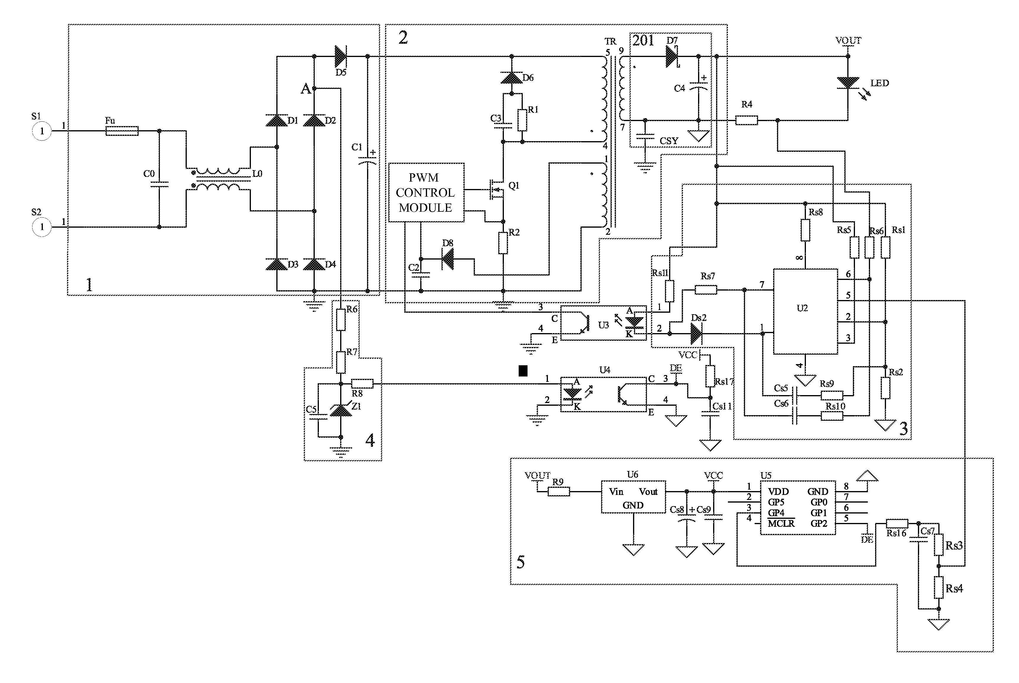
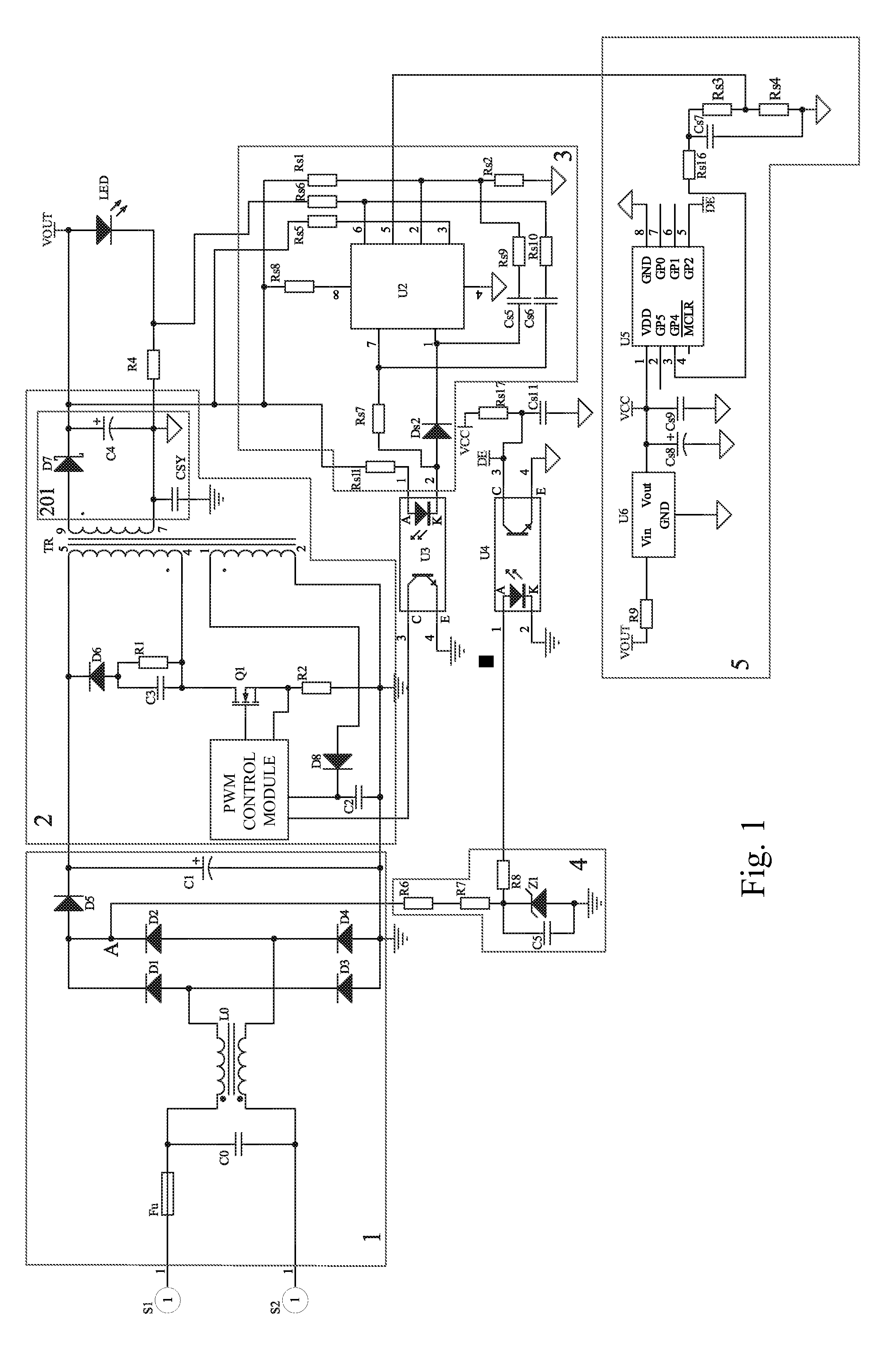
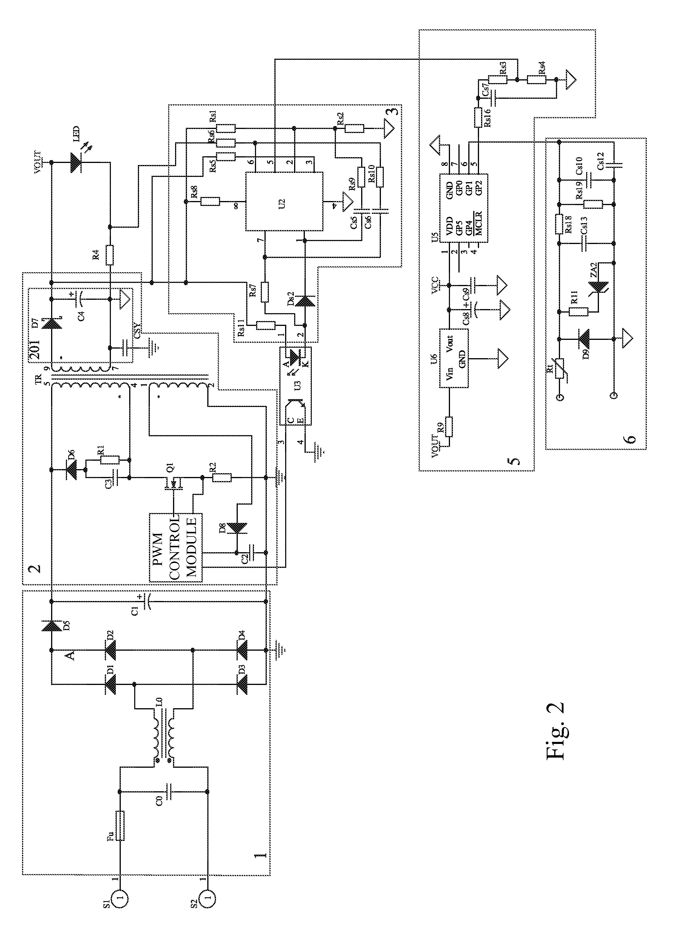
[0028]Generally, there are two approaches for controlling the brightness of a single LED. One of the approaches is to make use of the visual persistence of human eyes to realize brightness control with a pulse width modulation, namely to periodically change the pulse width (i.e. duty cycle) of emitted light. The human eyes would not get aware that a light emitting element is flickering provided that the cycle of light emission is short enough (i.e. the refresh rate is high enough). Since the pulse width modulation is preferably controlled in a digital way, a microcontroller is generally employed to provide driving signals for LED display, for example, almost all of the LED displays are effecting brightness control by means of pulse width modulation. The other approach would change the current flowing through the LED, namely to adjust the brightness of the LED lamp by controlling the output current of the power supply of the LED lamp. Except the saturation phenomenon found in red LED...


PUM


Abstract

The present invention relates to a novel dimming device for a LED lamp capable of effecting a stepped dimming of the LED lamp by detecting a momentary variation in on/off states of the power switch, enabling the LED lamp to vary to work in a plurality of working states in a cyclic manner according to a predetermined program. The dimming device the present invention overcomes the technical problems of using a regular power switch to effect dimming and allows the use of the regular power switch to effect the stepped dimming of LED lamp. The present invention may also use an external DC signal source to effect the stepped dimming of LED lamp. According to the present invention, a user may adjust the brightness of the LED lamp when needed, which not only facilitates the daily life of the user but also effectively save the energy.

Description

FIELD OF THE INVENTION[0001]The present invention relates to the field of light emitting diode (LED) illumination, and more particularly to a dimming device for LED lamp capable of performing stepped dimming.BACKGROUND OF THE INVENTION[0002]Along with the progress in science and technologies, semiconductor illumination devices, which are energy saving, environmental friendly and long in lifespan, have found a wide range of applications in various fields, particularly large power LED lamps. While in use, the illumination effect of a LED lamp sometimes may be affected if the lighting is too strong or relatively weak, therefore a dimming operation is desired. Presently, the LED lamp generally has a fixed luminance. The currently available dimming systems are usually relatively complicated and expensive, and thus cannot fulfill the different requirements of application environments.[0003]Japanese patent application no. JP 2007207734 A discloses a dimmable LED lamp, comprising a pluralit...

Claims


Application Information

Patent Timeline
IPC IPC(8): H05B37/02H05B44/00
CPCH05B33/0815H05B33/0848Y02B20/40Y02B20/346H05B37/0209H05B45/14H05B47/185Y02B20/30H05B45/385H05B45/30
Inventor FOO, ONN FAH
Owner MASS TECH (HK) LTD
Why Eureka
Try Eureka