Ice data collection system
a data collection and data technology, applied in underwater equipment, special-purpose vessels, instruments, etc., can solve the problems of increasing complexity, limited time available, and limited systems, and achieve the effect of increasing accuracy and accurately monitoring sea ice movement and thickness over a very large area
- Summary
- Abstract
- Description
- Claims
- Application Information
AI Technical Summary
Benefits of technology
Problems solved by technology
Method used
Image

Examples
example 1
[0032]In one embodiment, platform based UUVs are launched when an ice floe is identified. If the ice floe has one possible trajectory that may make it hazardous to the platform, a UUV launched from the platform is sent to the remote location where the ice floe is located. In one embodiment. A long range UUV may be launched with a radio transmitter. The UUV will assess the size, thickness and direction of the ice floe. Upon completion of the ice floe survey, the UUV will then attempt to surface within or near the ice floe of interest, this may be accomplished by identifying areas of no ice coverage within the survey area. Once the UUV surfaces within the ice floe of interest, it may transmit ice floe information directly to the platform or to one or more remote locations like a ship or receiving buoy. Not only will the ice floe thickness survey be transmitted via direct radio communication, but the ice floe location can be tracked with a low energy beacon. Once the hazardous ice floe...
example 2
[0033]In another embodiment, ice breakers in service around the platform to protect it from the ice also carry one or more UUVs. The UUVs are deployed from the ice breaker when an ice floe of interest is identified. In one embodiment, one ice breaker may be designated for ice floe management. The ice breaker is deployed to a distant location once the ice floe is identified. The UUV is released from that location and intercepts the ice floe. Once the ice floe is surveyed the UUV may return to the ice breaker. In one embodiment an underwater signal is used as a beacon to draw the UUV back to the ice breaker. In another embodiment, the UUV returns to a predetermined location to await retrieval. In yet another embodiment, the ice breaker may return to the UUV launch site for retrieval. The UUV may be launched and retrieved from any number of shipboard methods including moonpools, booms, winches, towed docking stations, or simply by tow line.
[0034]Additionally, one or more ice breakers m...
example 3
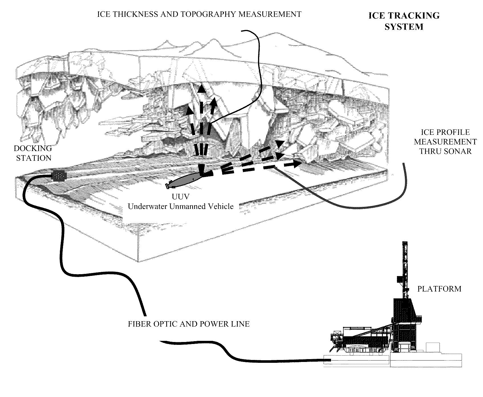
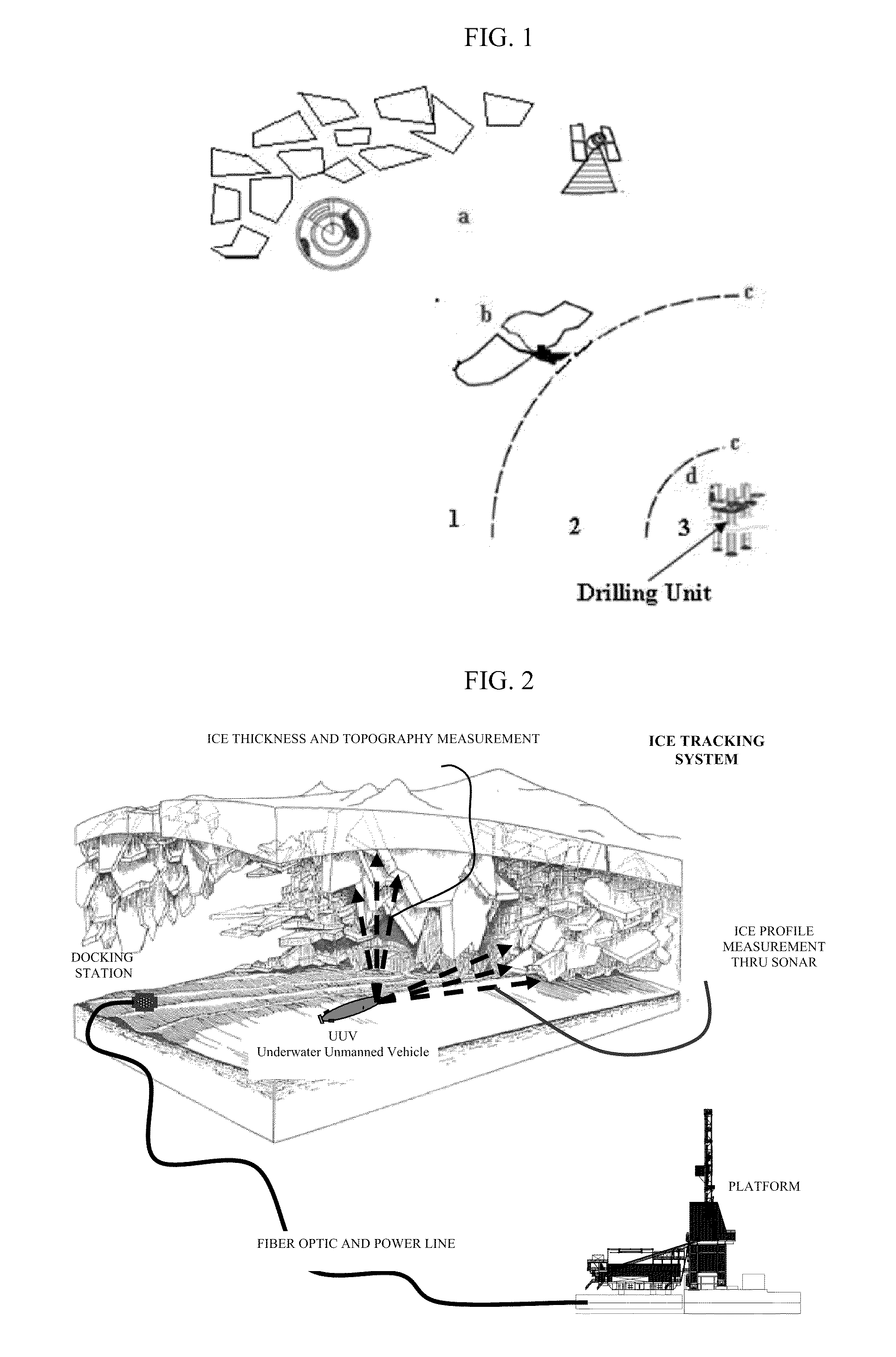
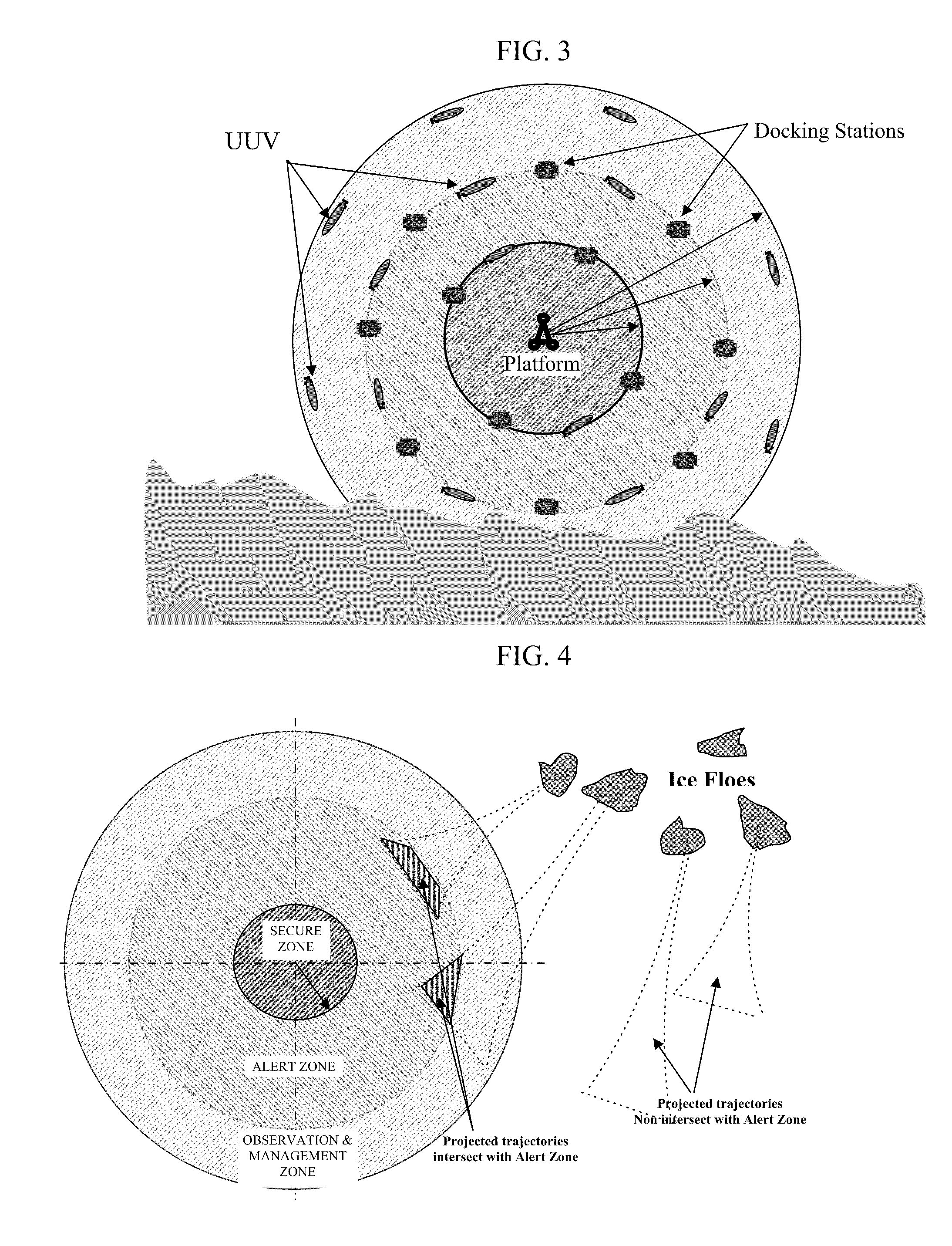
[0035]In another embodiment, docking stations are fixed on the sea bed. The docking system may be connected to the platform and can include a power source, data transmission wires, fiber optic systems, pressure sensors and the like. One or more UUVs may dock at a docking station for recharging, data download, or for “sleep” between surveys. UUVs are programmed to download the data they have stored on their memory and upload power to the batteries when docked as well as receive and transmit instructions, conditions, diagnostic information and the like. UUVs are programmed so that they “remember” where the docking stations are located and travel to the docking station if at any time communications are disrupted, the survey is unable to be completed, battery life is low, damage occurs, or other factors interfere with normal operations. FIG. 3 demonstrates one possible scenario of the location of the docking stations and the trajectory of the UUVs. Docking stations may be located at a s...
PUM
 Abstract
Description
Claims
Application Information
 - R&D
- Intellectual Property
- Life Sciences
- Materials
- Tech Scout
- Unparalleled Data Quality
- Higher Quality Content
- 60% Fewer Hallucinations
Browse by: Latest US Patents, China's latest patents, Technical Efficacy Thesaurus, Application Domain, Technology Topic, Popular Technical Reports.
© 2025 PatSnap. All rights reserved.Legal|Privacy policy|Modern Slavery Act Transparency Statement|Sitemap|About US| Contact US: help@patsnap.com