
Method and apparatus for enhanced eye measurement

a technology of enhanced eye measurement and eye image, applied in the field of enhanced eye image collection and processing, can solve problems such as inaccurate and less reproducible images, even measurement errors, and introduction of significant measurement errors

Active Publication Date: 2011-12-01
OPTOVUE
View PDF10 Cites 11 Cited by
  • Summary
  • Abstract
  • Description
  • Claims
  • Application Information

AI Technical Summary

Problems solved by technology

A shift in the position from this fixed distance could lead to inaccurate and less reproducible images, or even errors in measurements.
Since cornea is a high optical power surface, a small variation from a fixed distance between the subject eye and the imaging device can introduce significant measurement errors.
If the eye is moved away from the fixed distance at the focal point, the magnification of the virtual image would change and thus result in error of the topographic images or measurements.
However, the reference imaging method is highly subjective and difficult to perform for different face sizes and profiles.
The desirable fixed location cannot be achieved with high accuracy and repeatability using such method.
This triangulation beam method again is subject dependent and presents difficulties for the operator to locate the beam intersection on the cornea.
This approach can be uncomfortable for patient who is subjected to exposure of the multiple aiming beams and is also not user friendly due to the added complexity of additional light beams.
However, these methods are not very reliable because there are other factors affecting the quality and signal of the acquired images such as ambient light.

Method used


Image

  • Method and apparatus for enhanced eye measurement
  • Method and apparatus for enhanced eye measurement
  • Method and apparatus for enhanced eye measurement

Examples


Embodiment Construction

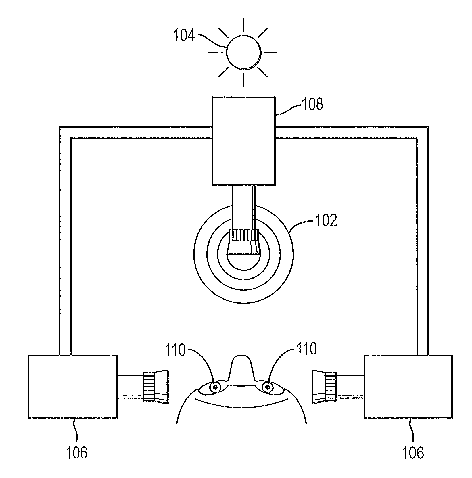
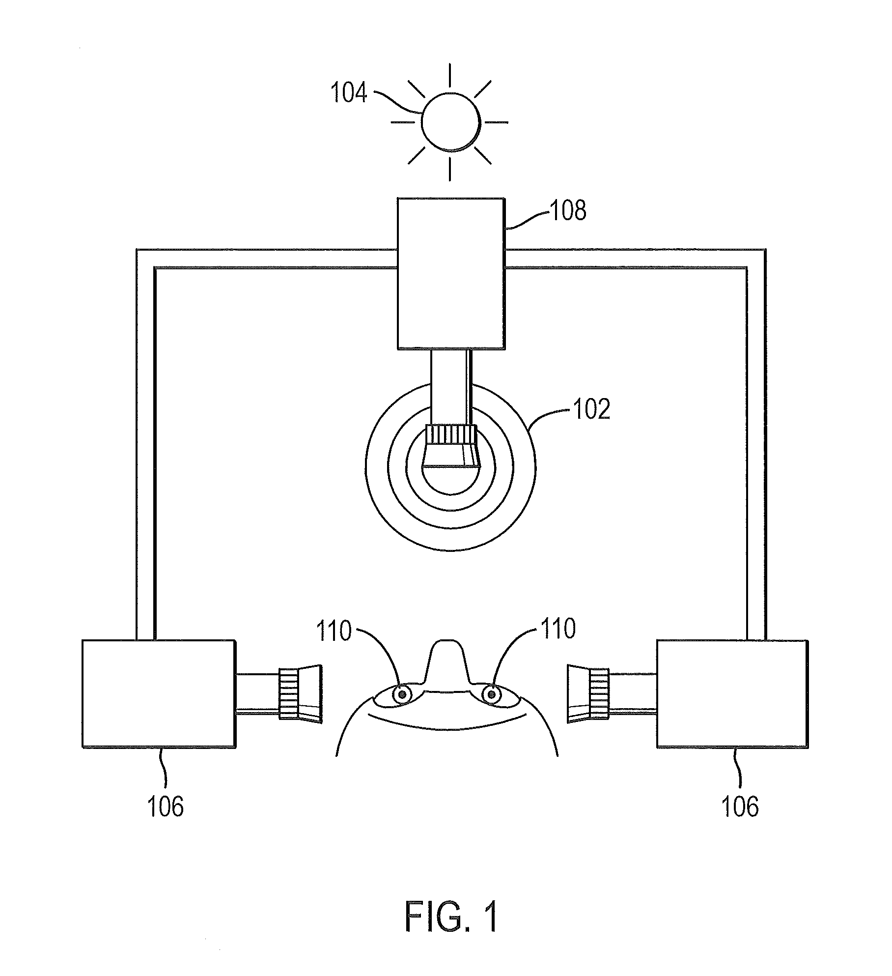
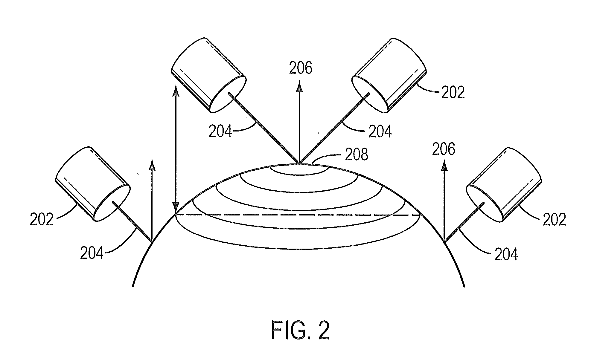
[0025]In accordance with some embodiments of the present invention, a method and an apparatus of determining an accurate and more reproducible position between a sample object and an imaging or measurement device is disclosed. Some embodiments below disclose methods and apparatus to enhance image reproducibility and accuracy of imaging instruments such as, for example, a topography system by incorporating an Optical Coherence Tomography (OCT) measurement. OCT is a very precise technique commonly used for imaging and measuring 3-D structure of biological tissue, for example, the human eye. The OCT technique can be applied together with other imaging systems to provide additional valuable information not available in the individual imaging systems to correlate, register and enhance the measurements and analysis. For example, a precise working distance between the subject eye and the imaging system can be determined by incorporating the OCT technique so that the eye can be placed at an...


PUM


Abstract

An imaging method according to some embodiments of the present invention includes obtaining working distance information from an optical coherence tomography system, the working distance being the working distance to the sample; obtaining information from one or more ocular systems; combining the information from said optical coherence tomography information and said ocular system; and displaying said combined information.

Description

RELATED APPLICATIONS[0001]This application claims priority to U.S. Provisional Application 61 / 350,258, filed on Jun. 1, 2010, which is herein incorporated by reference in its entirety.Background[0002]1. Field of Invention[0003]The embodiments described herein relate generally to methods and systems for collecting and processing images in ophthalmology.[0004]2. Background State of the Art[0005]To acquire accurate and repeatable images and measurements of a subject eye, it is desirable to image the subject eye at a fixed distance and at a reproducible location from the imaging device. Therefore, it is important to identify the desirable working distance (also known as the Z distance) between the subject eye and the imaging device. A shift in the position from this fixed distance could lead to inaccurate and less reproducible images, or even errors in measurements.[0006]Corneal topography, for example, is an imaging modality where acquiring accurate and repeatable images is important. ...

Claims


Application Information

Patent Timeline
Patent Type & Authority Applications(United States)
IPC IPC(8): A61B3/15A61B3/14
CPCA61B3/152A61B3/102
Inventor SOMANI, SEEMAWEI, JAY
Owner OPTOVUE
Learn More