Wiring structure for head suspension
- Summary
- Abstract
- Description
- Claims
- Application Information
AI Technical Summary
Benefits of technology
Problems solved by technology
Method used
Image

Examples
first embodiment
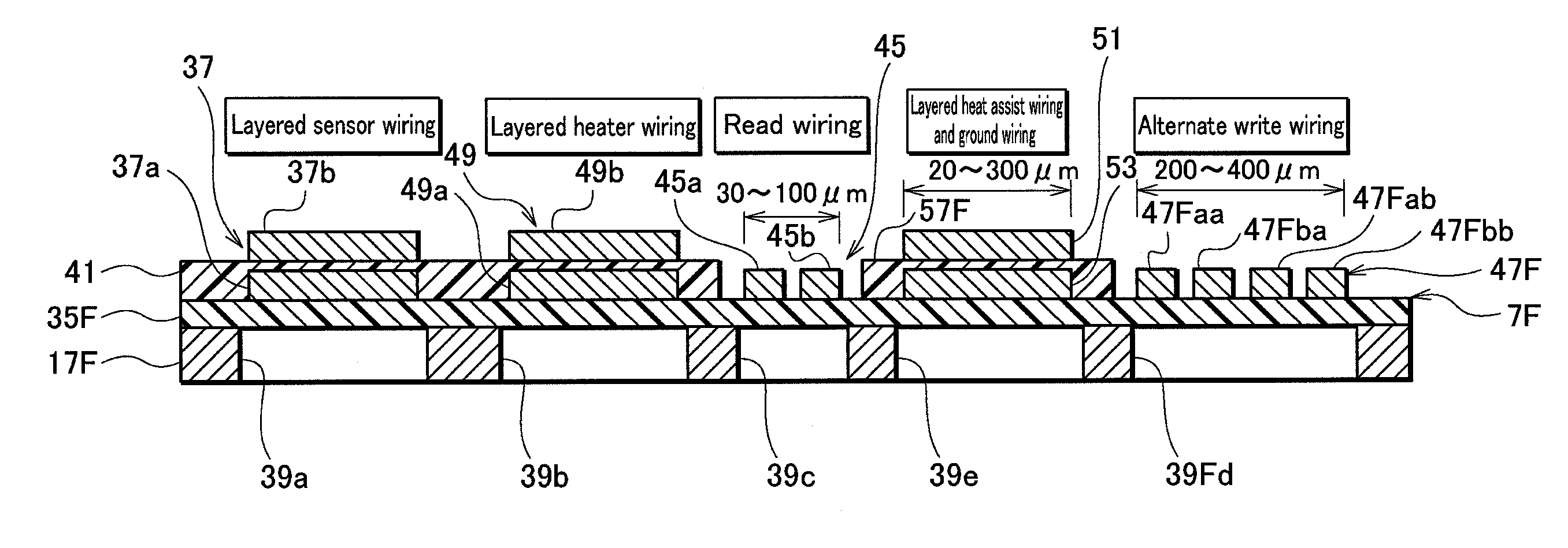
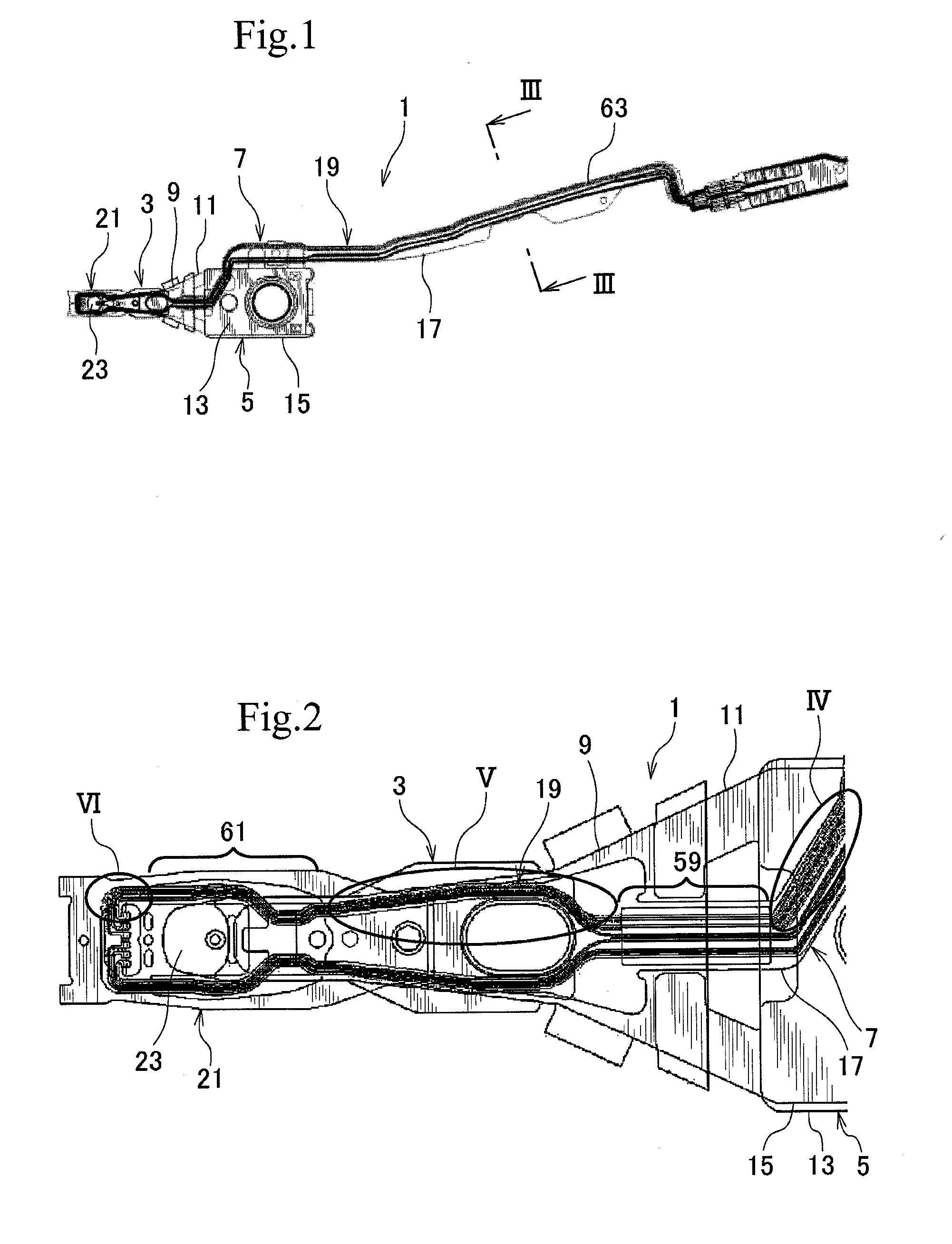
[0038]A head suspension employing a wiring structure according to the present invention will be explained with reference to FIGS. 1 and 2 in which FIG. 1 is a plan view illustrating the head suspension and FIG. 2 is an enlarged plan view illustrating a part of the head suspension.
[0039]As illustrated in FIGS. 1 and 2, the head suspension 1 has a load beam 3, a base 5, and a flexure 7.
[0040]The load beam 3 includes a rigid part 9 and a resilient part 11 to apply load onto a head 21. The rigid part 9 is made of, for example, stainless steel and is relatively thick, for example, about 100 μm.
[0041]The resilient part 11 is separate from the rigid part 9, is made of, for example, a resilient thin stainless steel rolled plate, and has a low and precision spring constant that is lower than that of the rigid part 9. The resilient part 11 has a thickness of about 40 μm. An end of the resilient part 11 is fixed to a rear end of the rigid part 9 by, for example, laser welding. The other end of...
second embodiment
[0077]A wiring structure for a head suspension according to the present invention will be explained with reference to FIG. 7 that is a sectional view at a location corresponding to the location of line III-III of FIG. 1.
[0078]A basic configuration of the second embodiment is the same as that of the first embodiment of FIG. 6, and therefore, the parts of FIG. 7 that are the same as or similar to those of FIG. 6 are represented with the same reference marks or the same reference marks plus “A” to omit overlapping explanation.
[0079]Similarly, the head suspension to which the wiring structure of the second embodiment is applied is the same as that of the first embodiment illustrated in FIGS. 1 and 2, and therefore, the details of the head suspension itself will not be explained. Only a characteristic part of the wiring structure according to the second embodiment will be explained.
[0080]According to the second embodiment, the head 21 additionally includes a near-field light emitter (pla...
third embodiment
[0087]A wiring structure for a head suspension according to the present invention will be explained with reference to FIG. 8 that is a sectional view at a location corresponding to the location of line III-III of FIG. 1.
[0088]A basic configuration of the third embodiment is the same as that of the first embodiment of FIG. 6, and therefore, the parts of FIG. 8 that are the same as or similar to those of FIG. 6 are represented with the same reference marks or the same reference marks plus “B” to omit overlapping explanation.
[0089]Similarly, the head suspension to which the wiring structure of the third embodiment is applied is the same as that illustrated in FIGS. 1 and 2, and therefore, the details of the head suspension itself will not be explained. Only a characteristic part of the wiring structure according to the third embodiment will be explained.
[0090]A flexure 7B having the wiring structure of the third embodiment includes write wiring 47B that is wider than read wiring 45 and...
PUM
 Abstract
Description
Claims
Application Information
 - R&D
- Intellectual Property
- Life Sciences
- Materials
- Tech Scout
- Unparalleled Data Quality
- Higher Quality Content
- 60% Fewer Hallucinations
Browse by: Latest US Patents, China's latest patents, Technical Efficacy Thesaurus, Application Domain, Technology Topic, Popular Technical Reports.
© 2025 PatSnap. All rights reserved.Legal|Privacy policy|Modern Slavery Act Transparency Statement|Sitemap|About US| Contact US: help@patsnap.com