
Mechanical oscillating system for clocks and functional element for clocks

a technology of mechanical oscillating system and functional element, which is applied in the direction of frequency stabilisation mechanism, instruments, horology, etc., can solve the problems of adverse effects of the accuracy of the oscillating system and/or non-reproducible conditions in production

Inactive Publication Date: 2011-12-01
DAMASKO
View PDF4 Cites 38 Cited by
  • Summary
  • Abstract
  • Description
  • Claims
  • Application Information

AI Technical Summary

Benefits of technology

[0004]It is therefore an object of the invention is to provide an oscillating system that avoids these disadvantages.
[0006]The invention is based on the knowledge that high accuracy, in particular temperature-independent accuracy, can be achieved especially easily in a mechanical oscillating system with a balance spring made of a non-metallic crystalline or sintered material with a grain size between 10 and 50,000 nm and with a linear thermal expansion coefficient smaller than 8×10⁻⁶ / K and / or of silicon through the use of molybdenum (Mo) for the oscillating body or the balance spring, and particularly in the case of a considerably reduced thickness of a silicon oxide coating of the balance spring.

Problems solved by technology

Especially when the silicon oxide layer has been applied thermally, in the case of layer thicknesses which would be required for optimal temperature compensation, i.e. in case of thicknesses greater than 4 μm, there is a danger of deformation, at least partial deformation of the balance spring, which then leads to adverse affects on the accuracy of the oscillating system and / or non-reproducible conditions in production.

Method used


Image

  • Mechanical oscillating system for clocks and functional element for clocks
  • Mechanical oscillating system for clocks and functional element for clocks
  • Mechanical oscillating system for clocks and functional element for clocks

Examples


Embodiment Construction

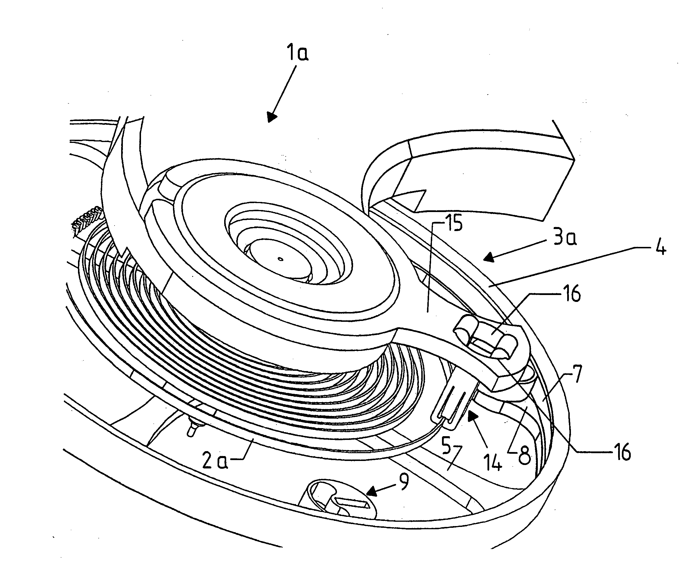
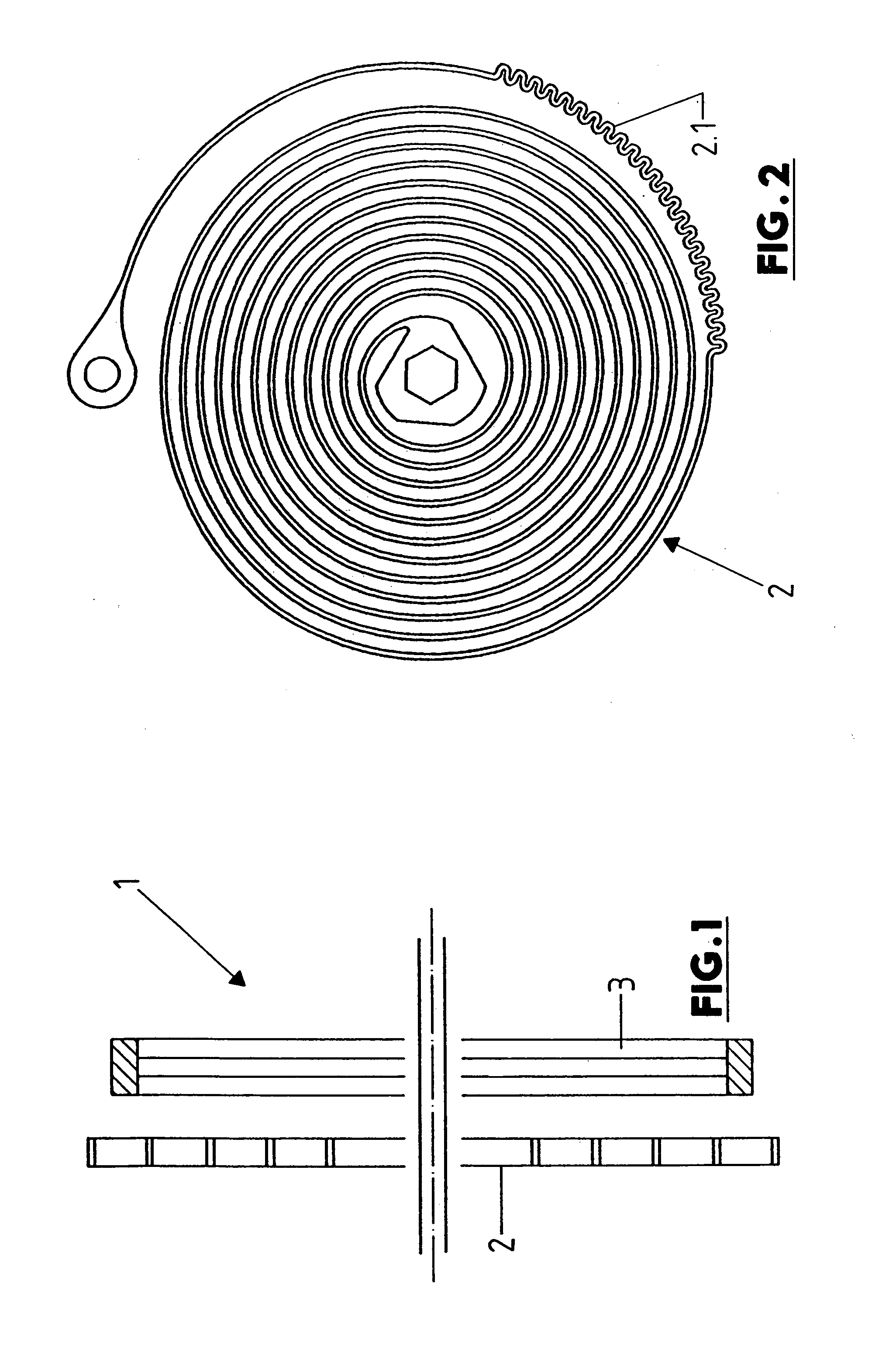
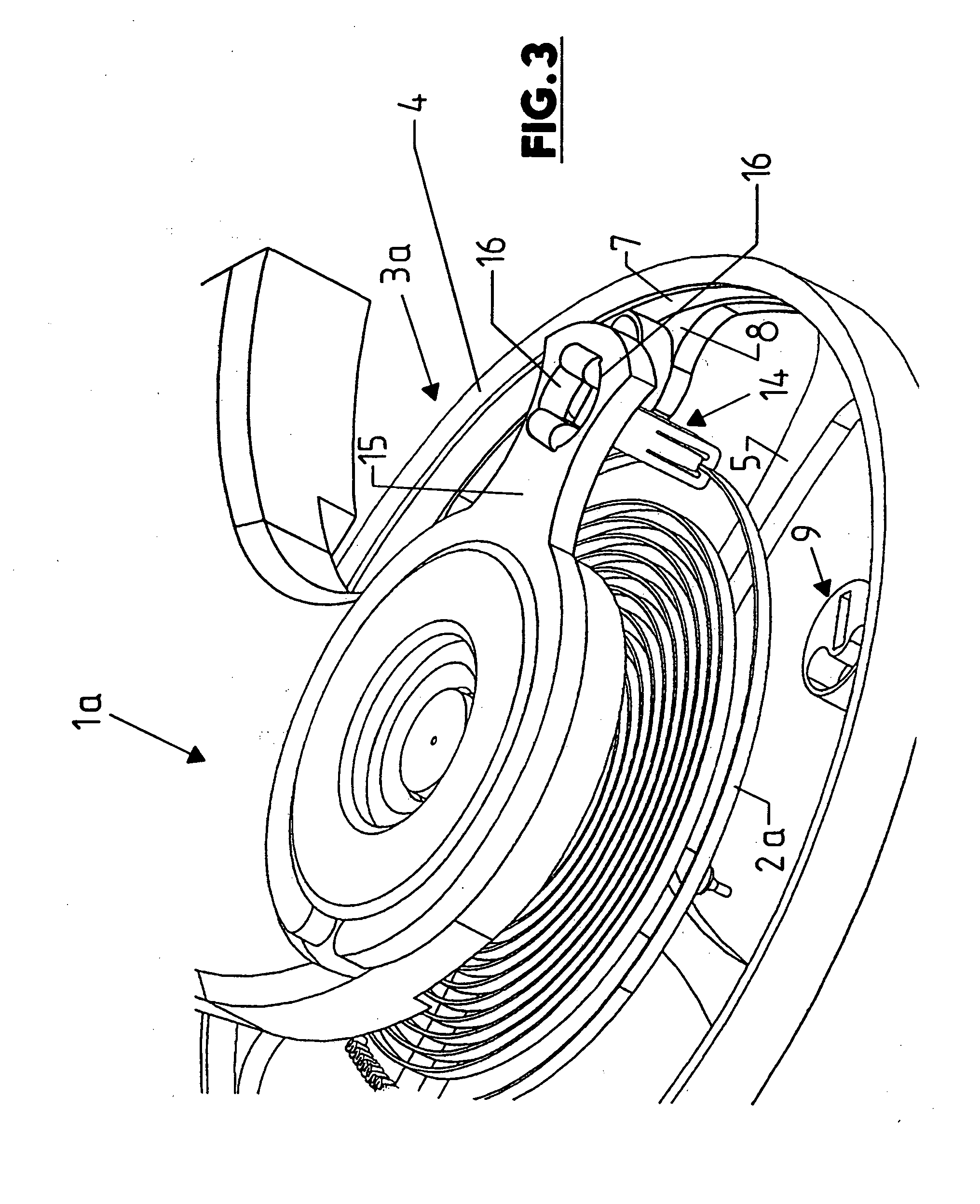
[0067]The oscillating system generally designated 1 in the drawing consists of the spiral spring 2 and the oscillating or balance wheel 3. The balance spring 2 is manufactured from silicon, preferably from polycrystalline silicon. The balance spring 2 is manufactured for example from a non-metallic crystalline or sintered material with a grain size between 10 and 50,000 nm, preferably between 10-10,000 nm, and the column growth of the grain size has a length for example of about 5-50 μm and a width of 10-1000 nm. Further, the non-metallic crystalline or sintered material has a linear thermal expansion coefficient smaller than 8×10⁻⁶ / K or the balance spring 2 is manufactured using a wafer from this material or from silicon, e.g. by cutting and / or etching (masking and etching technology). The wafer is produced for example by epitaxial deposition. The cross-sectional area of the spring winding is for example 0.001-0.01 mm2.

[0068]The balance spring 2 is provided on the outer surface of ...


PUM


Abstract

The invention relates to a mechanical oscillating system for watches, especially wrist watches, having a balance spring and an oscillating body.

Description

CROSS-REFERENCE TO RELATED APPLICATIONS[0001]This application is a national phase entry under 35 U.S.C. 371 of international application PCT / DE2010 / 000126 filed Feb. 4, 2010, which claims priority from DE102009007973.4 filed Feb. 6, 2009; DE102009013741.6 filed Mar. 20, 2009; DE102009025645.8 filed Jun. 17, 2009; DE102009030539.4 filed Jun. 24, 2009; DE102009031841.0 filed Jul. 3, 2009; DE102009050045.6 filed Sep. 24, 2009; DE102009048580.5 filed Oct. 7, 2009; DE102009060024.8 filed Dec. 21, 2009; DE102010004025.8 filed Jan. 4, 2010; DE102010005257.4 filed Jan. 20, 2010; DE102010006790.3 filed Feb. 4, 2010, the contents of which are incorporated herein by this reference.BACKGROUND OF THE INVENTION[0002]This invention relates to a mechanical oscillating system for clocks and to functional elements for clocks, especially in the form of spiral springs or oscillating bodies or spring retainer blocks.[0003]The prior art discloses manufacturing the spring or balance spring (spiral spring)...

Claims


Application Information

Patent Timeline
Patent Type & Authority Applications(United States)
IPC IPC(8): G04B17/06
CPCG04B17/066
Inventor DAMASKO, KONRAD
Owner DAMASKO
Learn More