
Image recording apparatus

a technology of image recording and recording medium, which is applied in the direction of printing, other printing apparatus, etc., can solve the problems of inability to record images at a high quality in some cases, inconvenient operation, and inability to maintain the interposing force or nipping force of the transport roller pair, so as to improve image quality and transport accuracy.

Active Publication Date: 2011-12-01
BROTHER KOGYO KK
View PDF12 Cites 2 Cited by
  • Summary
  • Abstract
  • Description
  • Claims
  • Application Information

AI Technical Summary

Benefits of technology

The present invention provides an image recording apparatus that can improve transport accuracy and achieve high-quality image recording by determining the rotation amount of a driving roller based on the position of a recording medium in a perpendicular direction. This allows for the use of the appropriate rotation amount of the driving roller regardless of the position of the recording medium, resulting in improved transport accuracy and image quality.

Problems solved by technology

However, the interposing force or nipping force of the transport roller pair, which is exerted on the recording medium, is not constant in some cases in the direction perpendicular to the transport direction of the transport roller pair.
It is impossible to record the image at a high quality in some cases.

Method used


Image

  • Image recording apparatus
  • Image recording apparatus
  • Image recording apparatus

Examples


Embodiment Construction

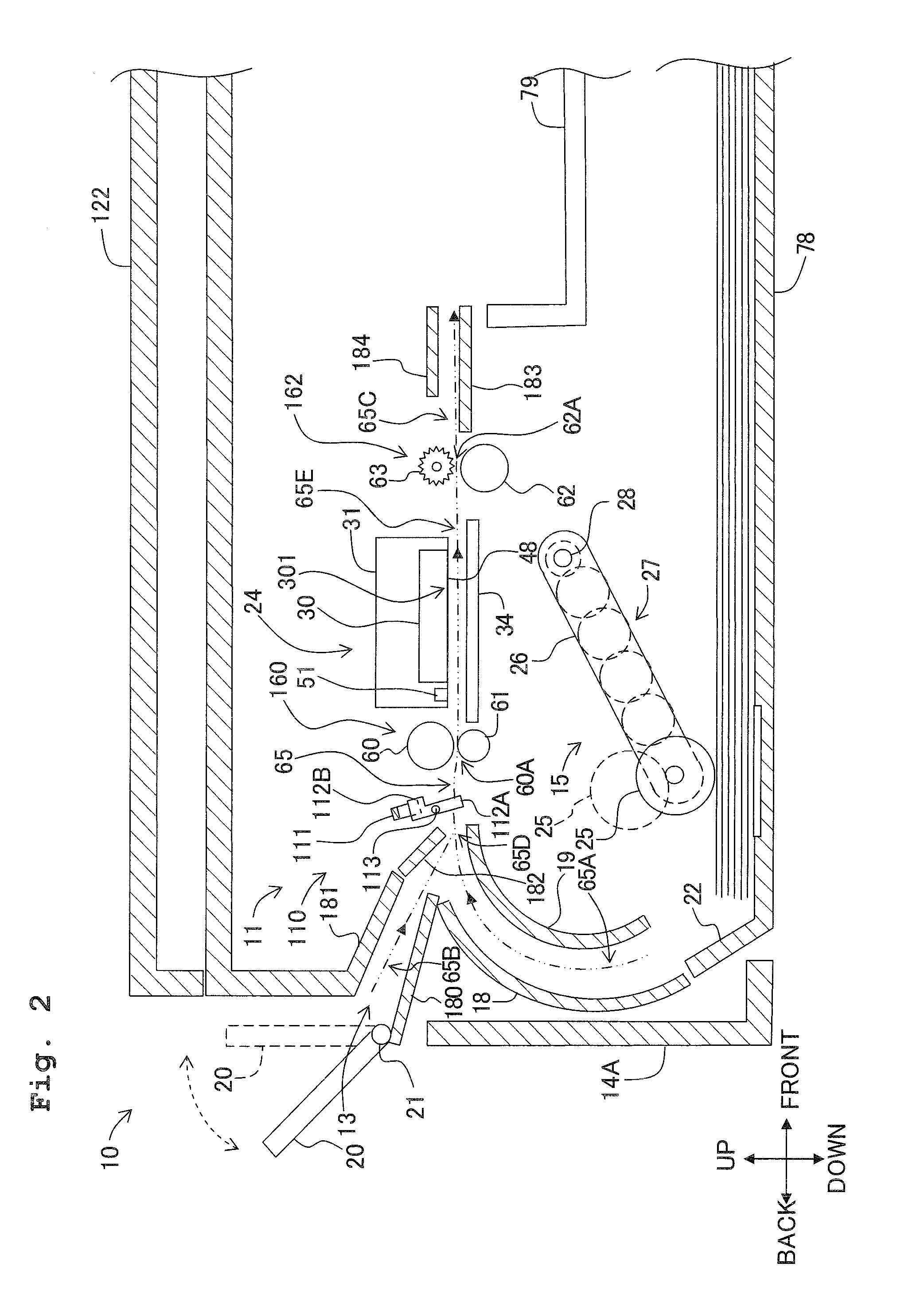
[0033]Preferred embodiments of the present invention will be explained appropriately below with reference to the drawings. It is noted that the embodiments explained below are merely examples of the present invention. It goes without saying that the embodiments of the present invention can be appropriately changed within a range without changing the gist or essential characteristics of the present invention.

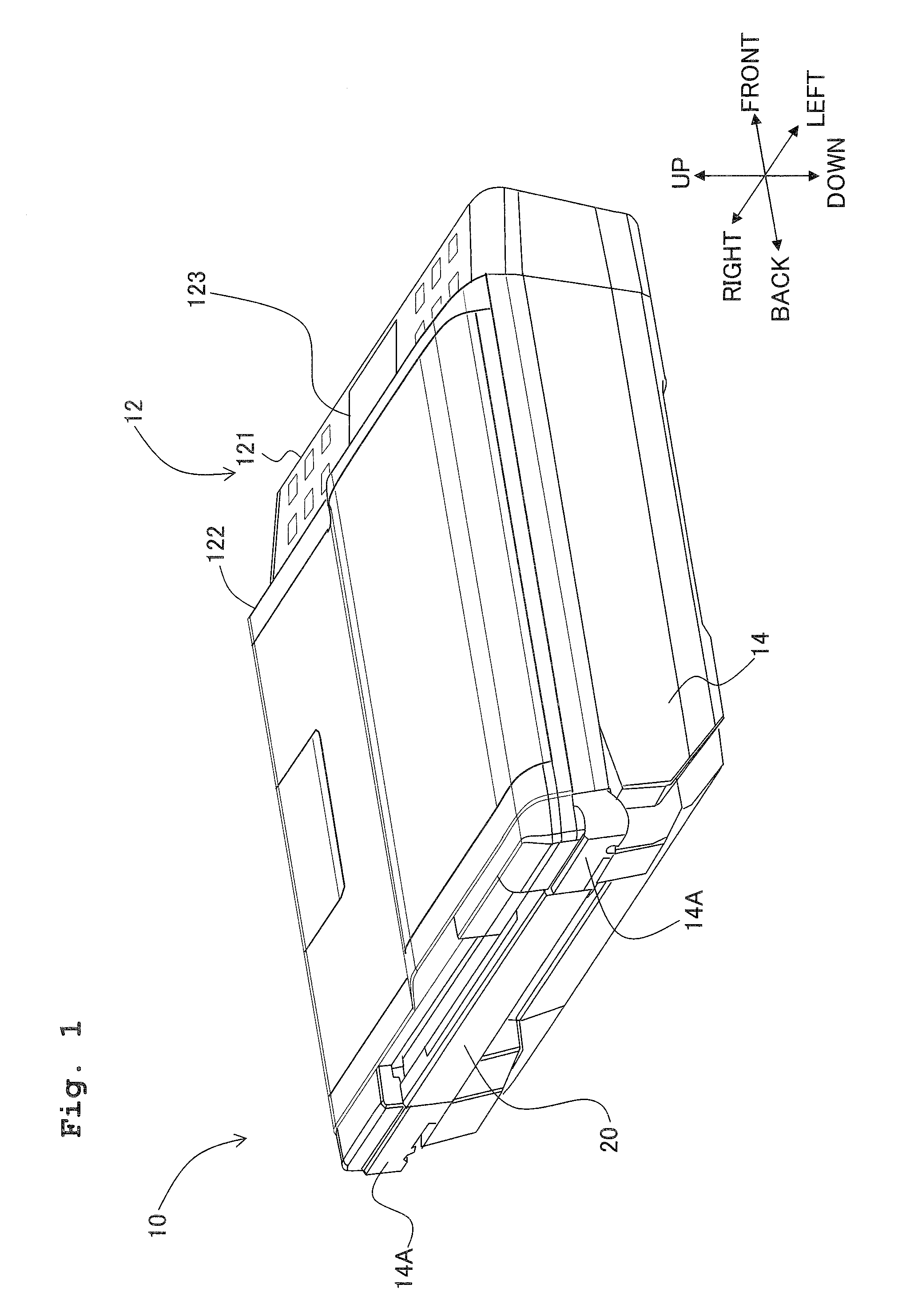
[0034]An explanation will be made with reference to FIG. 1 about a structure or arrangement of a multifunction machine 10 as an example of the image recording apparatus according to an embodiment of the present invention. In the following explanation, the upward-downward direction is defined based on a state (state shown in FIG. 1) in which the multifunction machine 10 is installed usably. The front-back direction (example of the first direction of the present invention) is defined assuming that the side, on which an operation panel 121 is provided, is the front side (front surfa...


PUM


Abstract

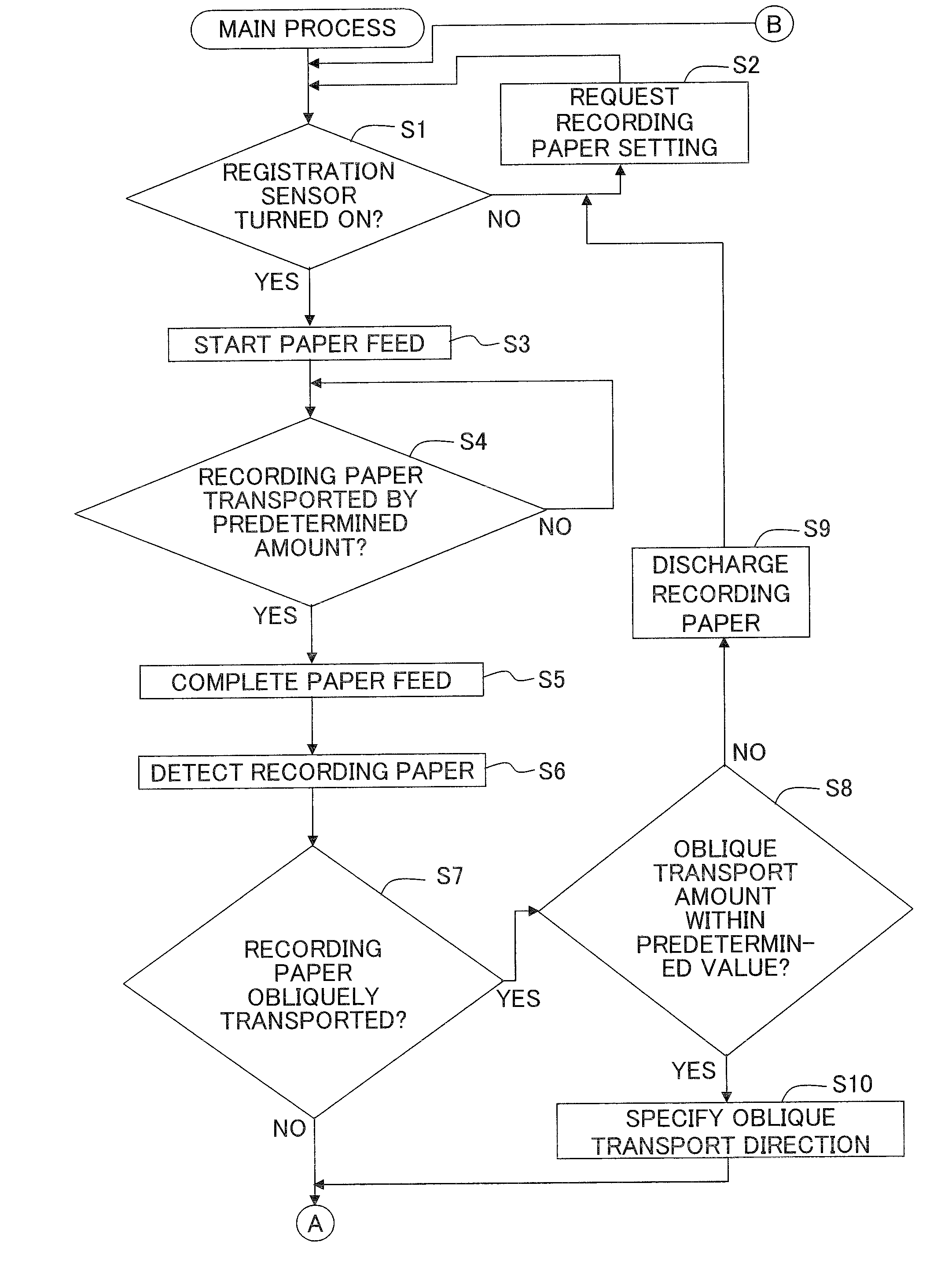
An image recording apparatus includes: at least one roller pair which has a driving roller and a driven roller facing the driving roller and which rotates while interposing the recording medium therebetween to transport the recording medium in a first direction; a recording section which records an image on the recording medium transported by the roller pair; a position detecting section which detects a position of the recording medium with respect to the roller pair in a second direction perpendicular to the first direction before the recording section starts recording; a determining section which determines a rotation amount of the driving roller before the recording section starts the recording depending on the position in the second direction of the recording medium detected by the position detecting section; and a control unit which controls the driving roller based on the rotation amount determined by the determining section.

Description

CROSS REFERENCE TO RELATED APPLICATION[0001]The present application claims priority from Japanese Patent Application No. 2010-119852, filed on May 25, 2010, the disclosure of which is incorporated herein by reference in its entirety.BACKGROUND OF THE INVENTION[0002]1. Field of the Invention[0003]The present invention relates to an image recording apparatus which records an image on a recording medium transported by a transport section. In particular, the present invention relates to the setting of the transport amount in relation to the transport section during the recording.[0004]2. Description of the Related Art[0005]Conventionally, an image recording apparatus, which is exemplified, for example, by a printer, a copying machine, and a facsimile, transports a recording medium such that the recording medium is interposed or nipped by a transport roller pair composed of a transport roller which uses a driving motor as a driving source and a driven roller which is arranged opposingly ...

Claims


Application Information

Patent Timeline
Patent Type & Authority Applications(United States)
IPC IPC(8): B41J11/42
CPCB41J11/42
Inventor HORADE, KENTA
Owner BROTHER KOGYO KK
Learn More