Lifting type multi-rotation self-positioning device

A self-positioning and lifting technology, which is applied in the direction of transportation and packaging, conveyors, mechanical conveyors, etc., can solve the problems of high precision, difficult maintenance and repair, and complicated parts, so as to reduce the probability of machine damage and improve transportation. The effect of improving production efficiency and transportation accuracy

Inactive Publication Date: 2018-12-25
江苏汉峰数控科技有限公司
View PDF0 Cites 0 Cited by
  • Summary
  • Abstract
  • Description
  • Claims
  • Application Information

AI Technical Summary

Problems solved by technology

[0003] In the current robot market, robots are generally heavy, with complex parts and high precision. Not only are they not easy to maintain and repair, but they are also extremely easy to wear parts during operation, and it is extremely difficult to repair parts after they are worn out. It needs to be parked as a whole, and the whole machine needs to be disassembled. Whether the mechanical design can be coordinated and operated is an important link in the design and production of robots. In the corresponding production process, there are special requirements for the design structure of the robot itself, and for The structure requirements of the robot itself are higher, and the robots at this stage can only meet the production requirements, and the requirements for further refined design
[0004] For the mechanical production and processing industry, accurate positioning and lifting functions have been widely used. However, the positioning in the prior art is only for the plane. When the lifting structure needs to be positioned in space, the positioning of the plane is far away. not able to meet the needs

Method used


Image

  • Lifting type multi-rotation self-positioning device

Examples


Embodiment Construction

[0016] The present invention will be further described below in combination with specific embodiments.

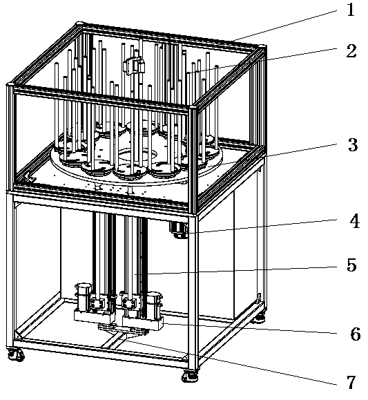
[0017] Such as figure 1 As shown, a lifting type multiple rotation self-positioning device includes an outer frame 1, a lifting support shaft 5 and a silo, an inner groove is arranged on the surface of the outer frame 1, and the inner groove is vertically downward, and the outer frame 1 includes Lifting support shaft 5, feed bin, outer frame 1 inner ring is provided with slide rail, outer frame 1 connects wallboard through slide rail, feed bin is fixedly connected with lifting support shaft 5, and between described feed bin and lifting support shaft 5 is provided with A partition, a rotating disk is arranged above the partition, a number of self-rotating disks 3 are uniformly arranged on the rotating disk along the edge of the rotating disk, and a buffer rubber ring is arranged below the center of the rotating disk 3, and the buffer rubber ring is a ring structure, self-po...


PUM


Abstract

The invention discloses a lifting type multi-rotation self-positioning device which comprises an outer frame, a lifting shaft and a stock bin, wherein the outer frame comprises a lifting support shaftand the stock bin; the stock bin is fixedly connected with the lifting support shaft to realize the lifting function of the stock bin; a partition board is arranged between the stock bin and the lifting support shaft to avoid influence of material falling to normal operation of a machine; a rotary disc is arranged above the partition board; a plurality of self-rotation discs are uniformly arranged on the rotary disc along the edge of the rotary disc, the independent areas and functions are divided, and the purpose of consistent integrity and substep operation is realized; the transportation processes of the integrity are divided into a plurality of parts, so that the transportation precision is improved, the positioning precision is greatly improved, and the problem that the positioning of excessive material is not precise during the transportation process is avoided; and what's more, the substep operation process can be simultaneously realized, so that the transportation time is shortened, and the transportation production efficiency is improved. The lifting type multi-rotation self-positioning device is widely applied to the field of mechanical production and processing.

Description

technical field [0001] The invention belongs to the technical field of mechanical automation, and more specifically relates to a lifting type multiple rotation self-positioning device. Background technique [0002] With the development of the times and the advancement of technology, it has become a mainstream trend to introduce robots as the main body of work in the process of mechanical production and processing. Robots are involved in all walks of life, such as CNC lathes, machining centers, truss robots, articulated arms Robots, etc., are distributed in all walks of life to work, and robots have high work efficiency, can work continuously for a long time, and the maintenance cost is relatively low compared with labor costs, which makes the application range of robots more and more extensive. [0003] In the current robot market, robots are generally heavy, with complex parts and high precision. Not only are they not easy to maintain and repair, but they are also extremely...

Claims


Application Information

Patent Timeline
IPC IPC(8): B65G35/00
CPCB65G35/00
Inventor 魏文权
Owner 江苏汉峰数控科技有限公司
Why Eureka
Try Eureka