Image reading device

a technology of image reading and reading roller, which is applied in the direction of thin material processing, digital output to print units, and article separation, etc., can solve the problems of increasing the size of the device, reducing the document transportation accuracy of the transportation roller, etc., and achieve the effect of reducing the cost of the devi

Active Publication Date: 2019-08-06
SEIKO EPSON CORP
View PDF6 Cites 0 Cited by
  • Summary
  • Abstract
  • Description
  • Claims
  • Application Information

AI Technical Summary

Benefits of technology

[0007]An advantage of some aspects of the invention is to provide an image reading device configured in consideration of both of improvement in transportation accuracy of a transportation roller that accurately feeds a document to a reader and suppression of an increase in size of the device.

Problems solved by technology

However, a backlash of a gear or distortion or the like of a rotation shaft causes a decrease in document transportation accuracy of the transportation roller.
However, when only the diameter of the gear is increased, the size of the device is increased.

Method used


Image

  • Image reading device
  • Image reading device
  • Image reading device

Examples


first example

Outline of Printer

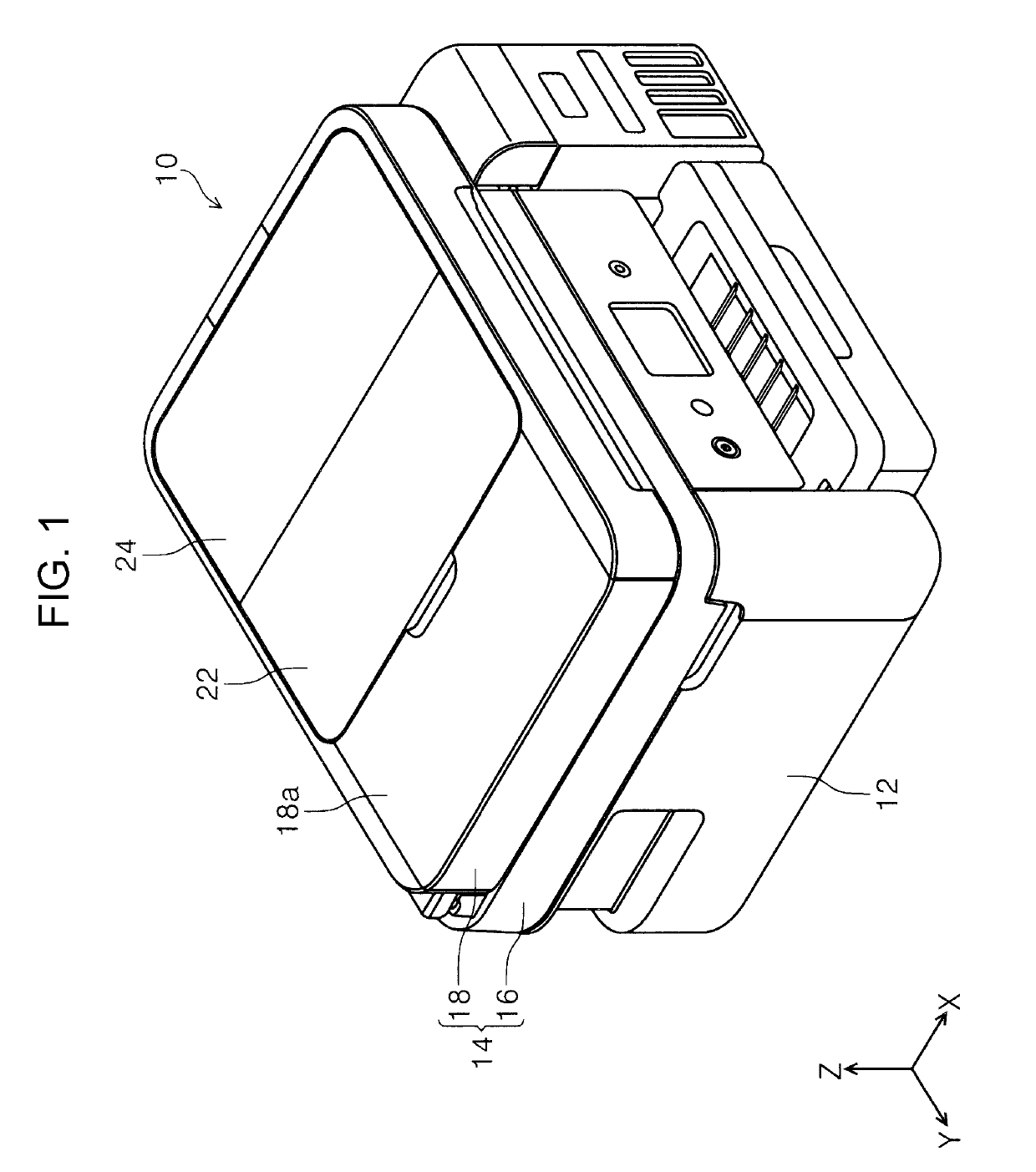
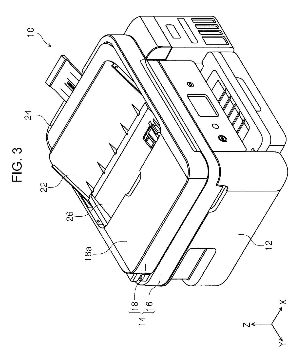
[0051]In FIG. 1, the entire configuration of a printer 10 will be described. The printer 10 is configured as an ink jet printer as an example of a recording device. The printer 10 is configured as a multifunction machine provided with a recording device section 12 and an image reading device 14. The image reading device 14 is configured as a scanner unit, for example.

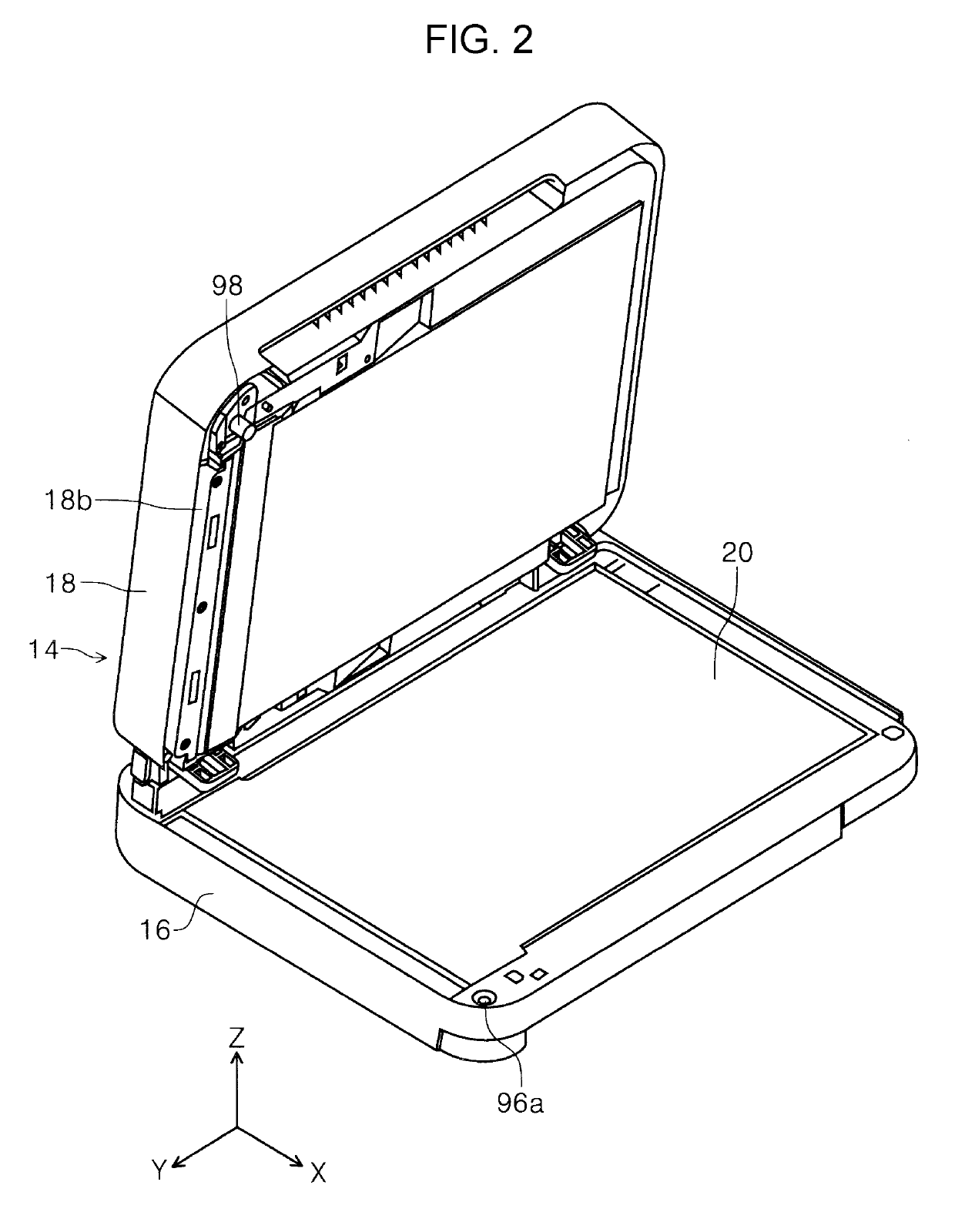
[0052]In this example, the image reading device 14 is rotatably connected to a rear surface side end portion of the recording device section 12 in the device depth direction. Although not shown in the drawings, when the image reading device 14 is rotated toward a device rear surface side, an upper portion of the recording device section 12 is exposed. The image reading device 14 is provided with a device main body 16 and a document transportation device 18. In this example, the document transportation device 18 is configured as an auto document feeder (ADF), for example.

[0053]In FIG. 2, the document tr...

modification example of example

[0102]In this example, a configuration, in which the power of the drive motor 56 (FIG. 16) is transmitted to the transportation roller driving gear 68B (FIG. 6) through the first bevel gear 58 (FIG. 5), the second bevel gear 60 (FIG. 5), the input gear 62 (FIGS. 5 and 6), and the fourth transmission gear 68A (FIG. 6) in a case where the composite gear 96 rotates in the counter-clockwise direction in FIG. 16, is adopted. However, instead of the above-described configuration, for example, a configuration in which, the composite gear 96 rotates in the clockwise direction in FIG. 16 as well while receiving the power of the drive motor 56, may be adopted. In this case, it is possible to adopt a configuration in which the transportation roller driving gear 68B directly meshes with the second input gear 62B without providing the fourth transmission gear 68A of the second gear group 68. As a result, it is possible to further reduce the number of gears of the second gear group 68.

[0103]A sum...


PUM

PropertyMeasurementUnit
poweraaaaaaaaaa
widthaaaaaaaaaa
drive poweraaaaaaaaaa

Abstract

There is provided an image reading device including a power transmission unit that transmits power of a driving source to a transportation roller and a discharging roller, in which the power transmission unit is configured to include a first gear group that constitutes a first power transmission route and a second gear group that constitutes a second power transmission route and that is configured to include a smaller number of gears than the first gear group, the second gear group includes a transportation roller driving gear and is disposed inside a curved inversion route as seen from an axial direction of a rotation shaft, and at least a portion of the transportation roller driving gear is positioned inside a medium transportation region in a width direction of a medium.

Description

BACKGROUND1. Technical Field[0001]The present invention relates to an image reading device that reads a surface of a medium.2. Related Art[0002]As a scanner which is an example of an image reading device, there is a scanner that is provided with an automatic document feeding device (also referred to as an auto document feeder (ADF)) and is configured to be capable of automatically feeding and reading a plurality of documents. As a configuration of the automatic document feeding device, there is a configuration in which a document is fed from a document supporting portion which supports the document, is transported to a reading position after being inverted in a U-shape, and is discharged toward a discharge tray after being read.[0003]In JP-A-2015-140255, an example of a scanner that is provided with such an automatic document feeding device is described.[0004]There is a case where a number of rollers are provided in a document transportation path in an automatic document feeding dev...

Claims


Application Information

Patent Timeline
Patent Type & Authority Patents(United States)
IPC IPC(8): H04N1/00B65H5/06B65H29/14B65H29/12B65H31/02B65H29/20B65H3/06G06F3/12
CPCH04N1/00618B65H3/0684B65H5/06B65H5/062B65H29/125B65H29/14B65H29/20B65H31/02H04N1/00602H04N1/00652H04N1/00798B65H3/0669B65H2405/11151B65H2301/4212B65H2403/42B65H2403/43B65H2403/73B65H2404/6111B65H3/06H04N1/0057H04N1/04B65H2801/03
Inventor KOZAKI, KOHEIMIYAMOTO, SHINTAROTAMAI, KENSUKE
Owner SEIKO EPSON CORP
Why Eureka
Try Eureka