Centrifugal Separator

a centrifugal separator and centrifugal technology, applied in centrifuges, filtration separation, separation processes, etc., can solve the problems of increasing the efficiency of the separator and reducing the entrainment of solids, so as to reduce the occurrence of turbulence, reduce the tendency of the vortex, and reduce the effect of turbulen

Inactive Publication Date: 2011-12-01
CLAUDE LAVAL
View PDF0 Cites 16 Cited by
  • Summary
  • Abstract
  • Description
  • Claims
  • Application Information

AI Technical Summary

Benefits of technology

[0010]Surprisingly, the inventor herein has observed that the presence of the axially-centered rod between the spin plate and the outlet barrel reduces the occurrence of turbulence in the portion of the separation barrel in axial adjacency with the spin plate. Moreover, the presence of the rod stabilizes the axial position of the vortex. This stabilization reduces the tendency of the vortex, particularly in the portion of the separation barrel near the spin plate, to migrate into the path of the oncoming solids-laden stream, which is flowing tangentially along the inner wall toward the spin plate.
[0011]Decreasing the turbulence in the barrel adjacent to the spin plate and also decreasing the intrusion of the vortex into the oncoming solids-laden stream substantially reduces the entrainment of solids in the vortex, and thus increases the efficiency of the separator. The inventor herein has further found that there is even greater stabilization of the vortex and reduced tendency for turbulent flow to be induced if the spin plate itself is formed by the top surface of a truncated cone, where the truncated cone comprises the top surface, a base, and a conical surface extending from the base to the top surface and the truncated cone is disposed between the separation chamber and the collection chamber. The collection chamber may also have a larger diameter than the separation barrel.

Problems solved by technology

Decreasing the turbulence in the barrel adjacent to the spin plate and also decreasing the intrusion of the vortex into the oncoming solids-laden stream substantially reduces the entrainment of solids in the vortex, and thus increases the efficiency of the separator.

Method used


Image

  • Centrifugal Separator
  • Centrifugal Separator
  • Centrifugal Separator

Examples


Embodiment Construction

Description of the Prior Art Separator

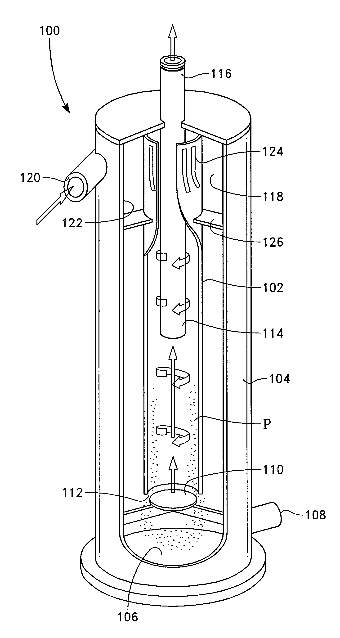
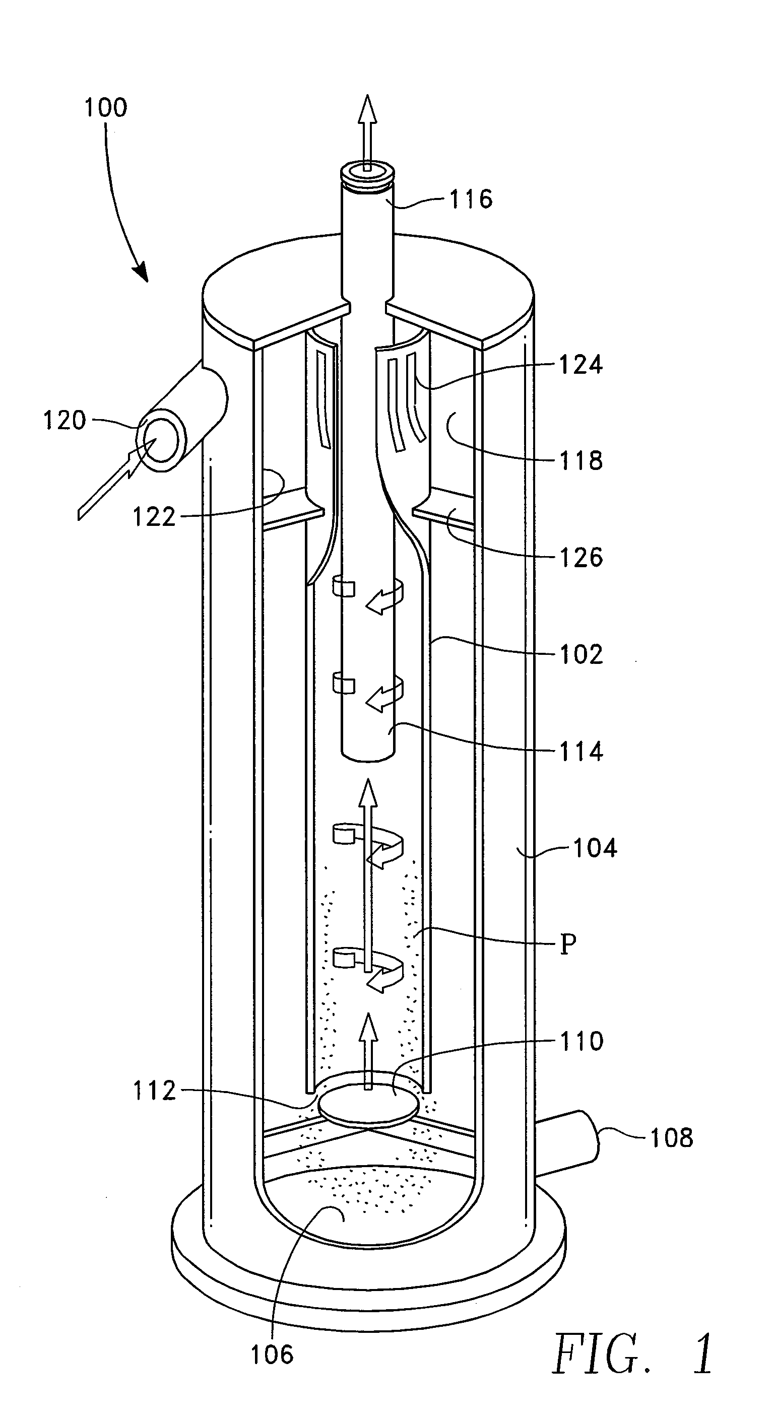
[0022]FIG. 1 depicts a known centrifugal separator 100. Its basic functional element is a separation barrel 102 which is contained within an outer housing 104. A collection chamber 106 is placed at the lower end of the outer housing 104 where the collection chamber collects separated solids P, from the downward liquid flow, which is illustrated by the clockwise arrows within the separation barrel. This downward liquid flow may contain a high concentration of entrained solids, which are forced against the interior wall of the separation barrel by centrifugal force. A drain port 108 at the bottom end of the collection chamber 106 enables the solids and some liquids to be drawn from it, either continuously or from time to time. At or near the lower end of the separation barrel 102 there is a spin plate 110 which extends normal to the central axis of the separation barrel. A slot 112 or other conduit means is left between the spin plate 110 and the ...


PUM

PropertyMeasurementUnit
angleaaaaaaaaaa
angleaaaaaaaaaa
spin structureaaaaaaaaaa

Abstract

A centrifugal separator having a separation chamber and a collection chamber utilizes an axially-oriented structure which extends from the spin structure, or spin plate, up and into the vortex finder. The axially-oriented structure decreases turbulence within portion of the separator in axial adjacency with the spin structure, including the separation chamber in which the solids are collected. The reduction of turbulence substantially reduces the entrainment of solids in the rising stream of liquid flowing to the vortex finder, and thus increases the efficiency of the separator. The spin structure may comprise a truncated cone mounted with a portion of the truncated cone in the separation chamber and the remainder in the collection chamber.

Description

BACKGROUND OF THE INVENTION[0001]The disclosed device generally relates to devices used to separate solids from liquids, and specifically to an improved centrifugal separator which includes internal structure which enable the attainment of preferred flow regimes through the separator, resulting in superior separation of solids from the liquid and greater efficiency in operation of the separator.[0002]Centrifugal separators are generally known as a means to separate solids from flowing streams of fluid in which the solids are entrained. The typical configuration of a centrifugal separator is to inject a stream of the influent through a nozzle tangentially into a cylindrical separation barrel. As the injected stream whirls around the inside wall of the separation barrel, the high g forces within the stream cause the solid particles to migrate toward the wall as the whirling stream flows from one end of the separation barrel to the other, typically from an upper elevation to a lower el...

Claims


Application Information

Patent Timeline
Patent Type & Authority Applications(United States)
IPC IPC(8): B04B11/08
CPCB04C5/04B04C5/107B04C2005/136B04C5/181B04C5/13
Inventor FORD, STEVEN D.
Owner CLAUDE LAVAL
Why Eureka
Try Eureka