
Device for treating evaporated fuel

a technology for treating devices and evaporated fuel, which is applied in the direction of combustion air/fuel air treatment, machines/engines, transportation and packaging, etc., can solve the problems of fuel consumption deterioration, exhaust gas heat may not be used for heating the canister, etc., and achieve the effect of improving desorption efficiency

Inactive Publication Date: 2011-12-08
TOYOTA JIDOSHA KK
View PDF3 Cites 16 Cited by
  • Summary
  • Abstract
  • Description
  • Claims
  • Application Information

AI Technical Summary

Benefits of technology

The present invention relates to an evaporated fuel treating device for vehicles that improves desorption efficiency even in a state in which there is little exhaust heat from the engine. The invention includes a fuel tank, a rechargeable battery, and a canister that adsorbs evaporated fuel produced in the fuel tank. The canister is heated by the rechargeable battery, and the heat is transferred to the canister to improve desorption efficiency. The invention also includes a structure in which the canister is located close to the rechargeable battery to efficiently use space between the fuel tank and the rechargeable battery. The technical effect of the invention is to improve the efficiency of evaporated fuel treatment in vehicles that run with a combination of engine and motor.

Problems solved by technology

Therefore, heat of the exhaust gas may not be used for heating of the canister when the engine is stopped.
Driving the engine just to desorb evaporated fuel would lead to problems such as a deterioration in fuel consumption and the like.

Method used


Image

  • Device for treating evaporated fuel
  • Device for treating evaporated fuel
  • Device for treating evaporated fuel

Examples


Embodiment Construction

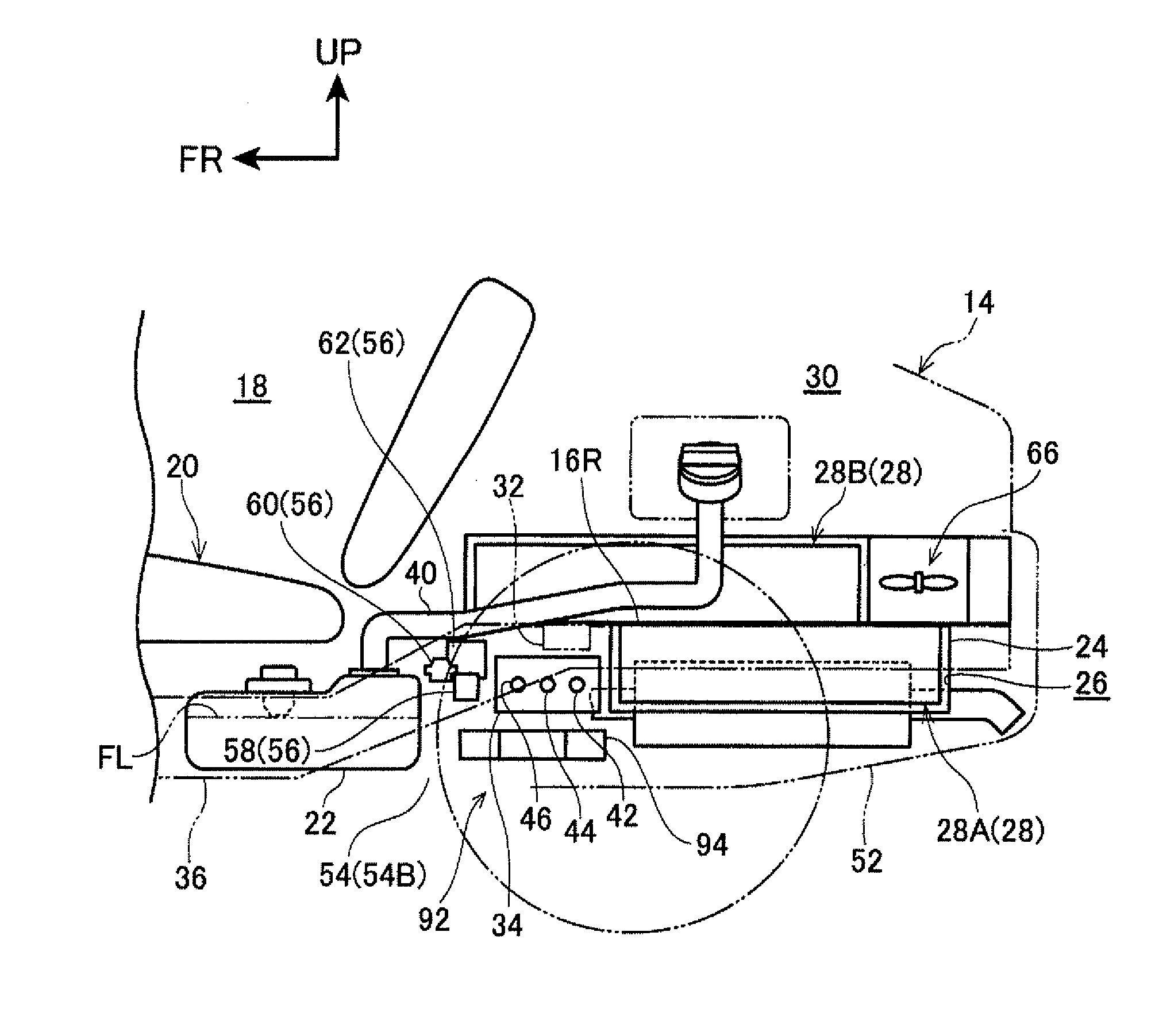
[0036]FIG. 3 and FIG. 4 schematically illustrate a rear portion of a vehicle 14 in which an evaporated fuel treating device 12 of a first exemplary embodiment of the present invention is deployed. The vehicle 14 is equipped with an engine and a motor (neither of which is illustrated), both of which serve as drive sources of the vehicle 14 and exert drive power.

[0037]In these drawings, forward in the vehicle is indicated by the arrow FR, sideward in the vehicle is indicated by the arrow W, and upward is indicated by the arrow UP. The meanings of the terms “forward” and “rearward” when used alone hereinafter are intended to include, respectively, forward in the vehicle and rearward in the vehicle.

[0038]The vehicle 14 is provided with a seat 20 mounted inside a cabin 18. Therebelow, a fuel tank 22 is mounted by unillustrated mounting members (tank bands or the like).

[0039]A floor pan 24 is provided in a rear floor panel 16R rearward of the seat 20. At the floor pan 24, the rear floor p...


PUM


Abstract

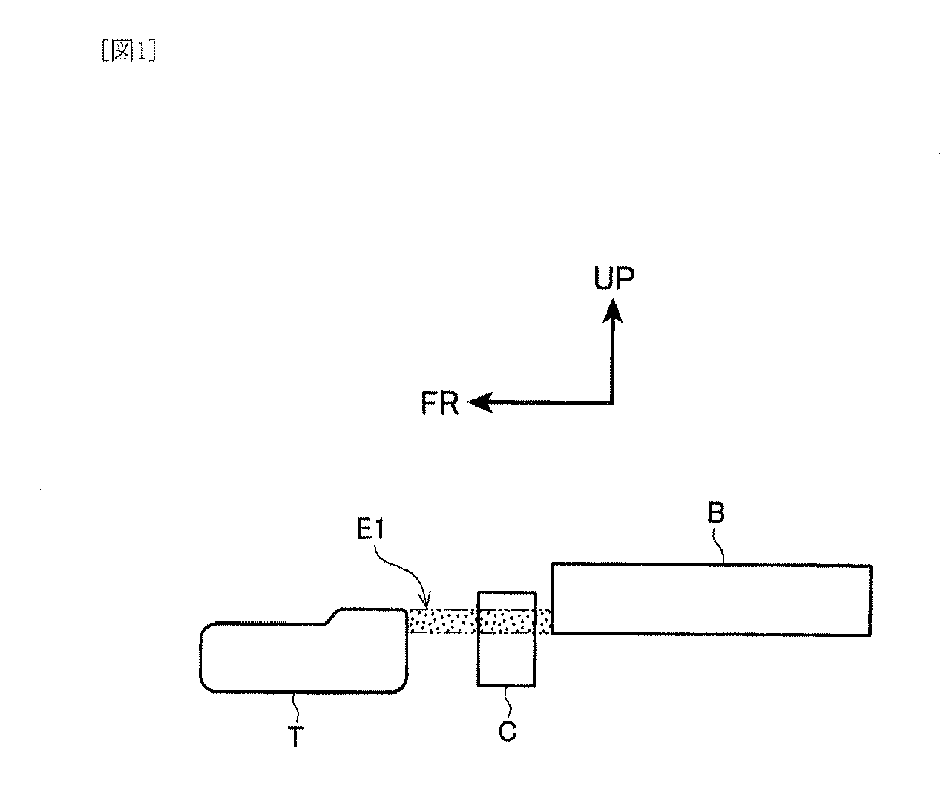
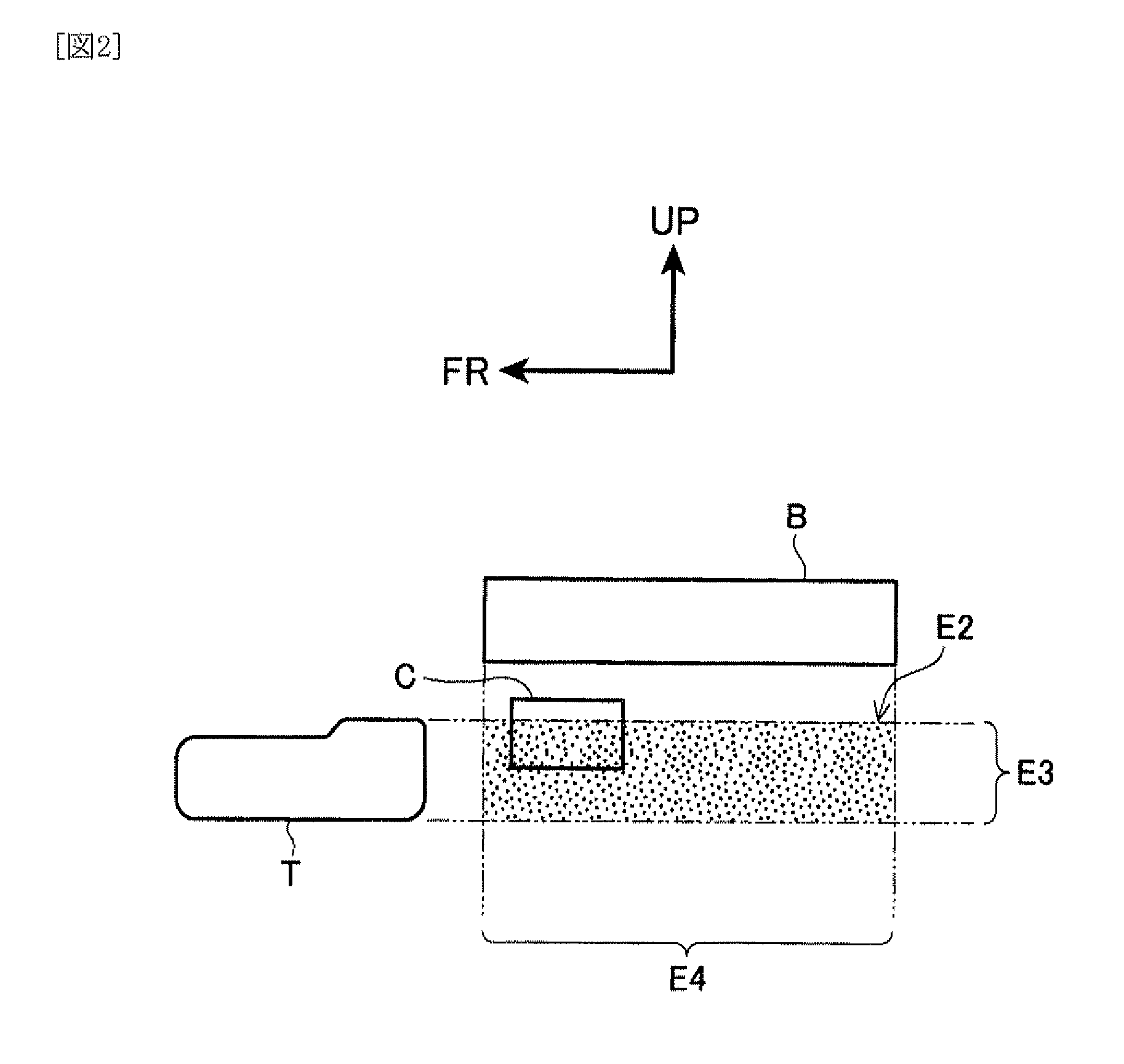
In a vehicle that runs by drive power of a motor in addition to that of an engine, a device for treating evaporated fuel is provided that may heat a canister and improve desorption efficiency even in a state in which there is little exhaust heat from the engine. A vehicle is provided with a first battery and a second battery. A canister is disposed in front of the first battery and below the second battery. Because the canister is disposed near to the batteries, heat is transferred from the batteries to the canister and an adsorbing agent in the canister is heated.

Description

TECHNICAL FIELD[0001]The present invention relates to an evaporated fuel treating device for treating evaporated fuel that is produced in a fuel tank.BACKGROUND ART[0002]A canister adsorbs evaporated fuel from a fuel tank or the like with an adsorbing agent, and an improvement in desorption (purging) efficiency of the adsorbed evaporated fuel is desired. In Patent Reference 1, with regard thereto, a system is recited in which an adsorbing agent in a canister is efficiently heated by the heat of exhaust gas passing through an exhaust pipe of a vehicle, and desorption of the fuel from the adsorbing agent is promoted.[0003]In a hybrid vehicle that runs by appropriately using the drive power of a motor as well as an engine, because of the driving of the motor, driving periods of the engine may be shorter.[0004]However, when the driving periods of the engine are shorter in this manner, exhaust gas does not flow through the exhaust pipe when the engine is stopped. Therefore, heat of the e...

Claims


Application Information

Patent Timeline
Patent Type & Authority Applications(United States)
IPC IPC(8): F02M25/08F01N5/02
CPCF02M25/0854F02M25/089Y10S903/951Y10S903/904Y10S903/907Y10S903/903
Inventor ASO, SHUICHI
Owner TOYOTA JIDOSHA KK
Learn More