

Evaporated fuel treatment apparatus
- Summary
- Abstract
- Description
- Claims
- Application Information
AI Technical Summary
Benefits of technology
Problems solved by technology
Method used
Image

Examples
first embodiment
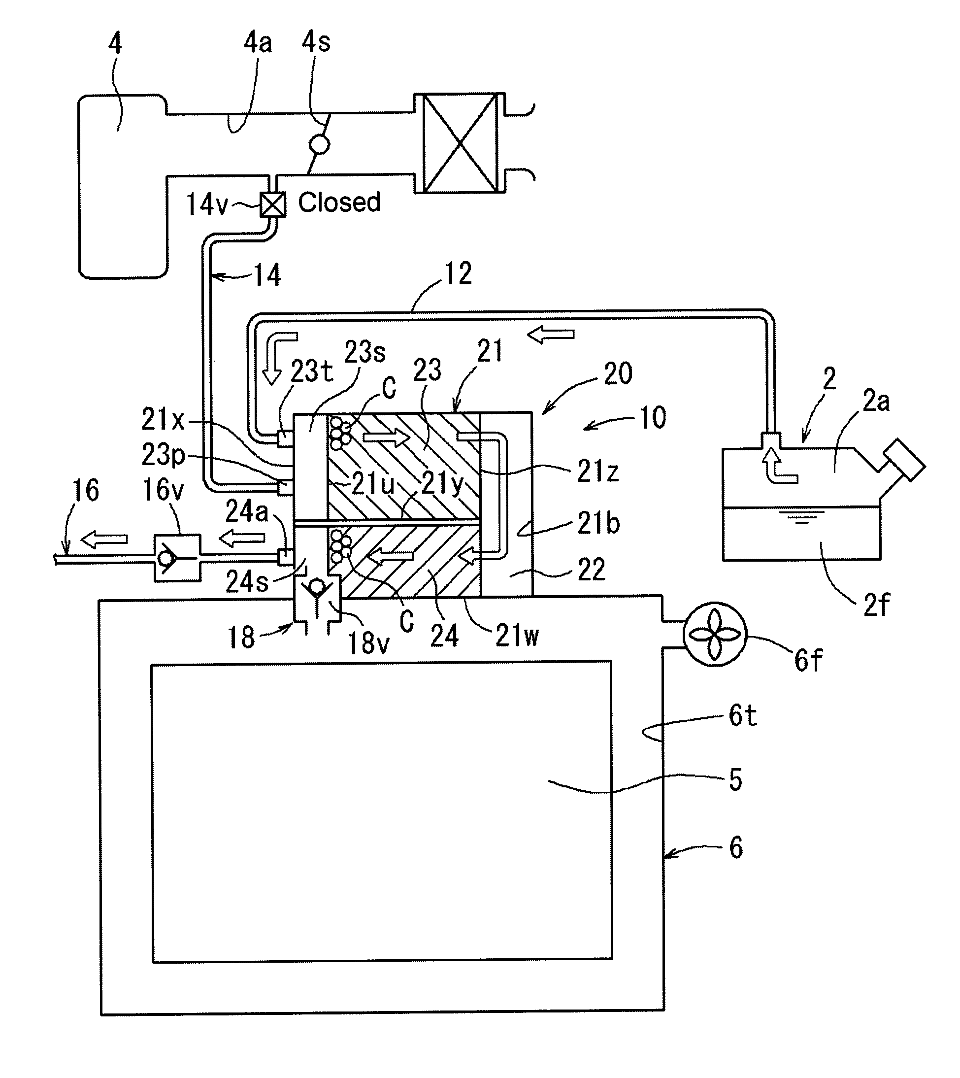
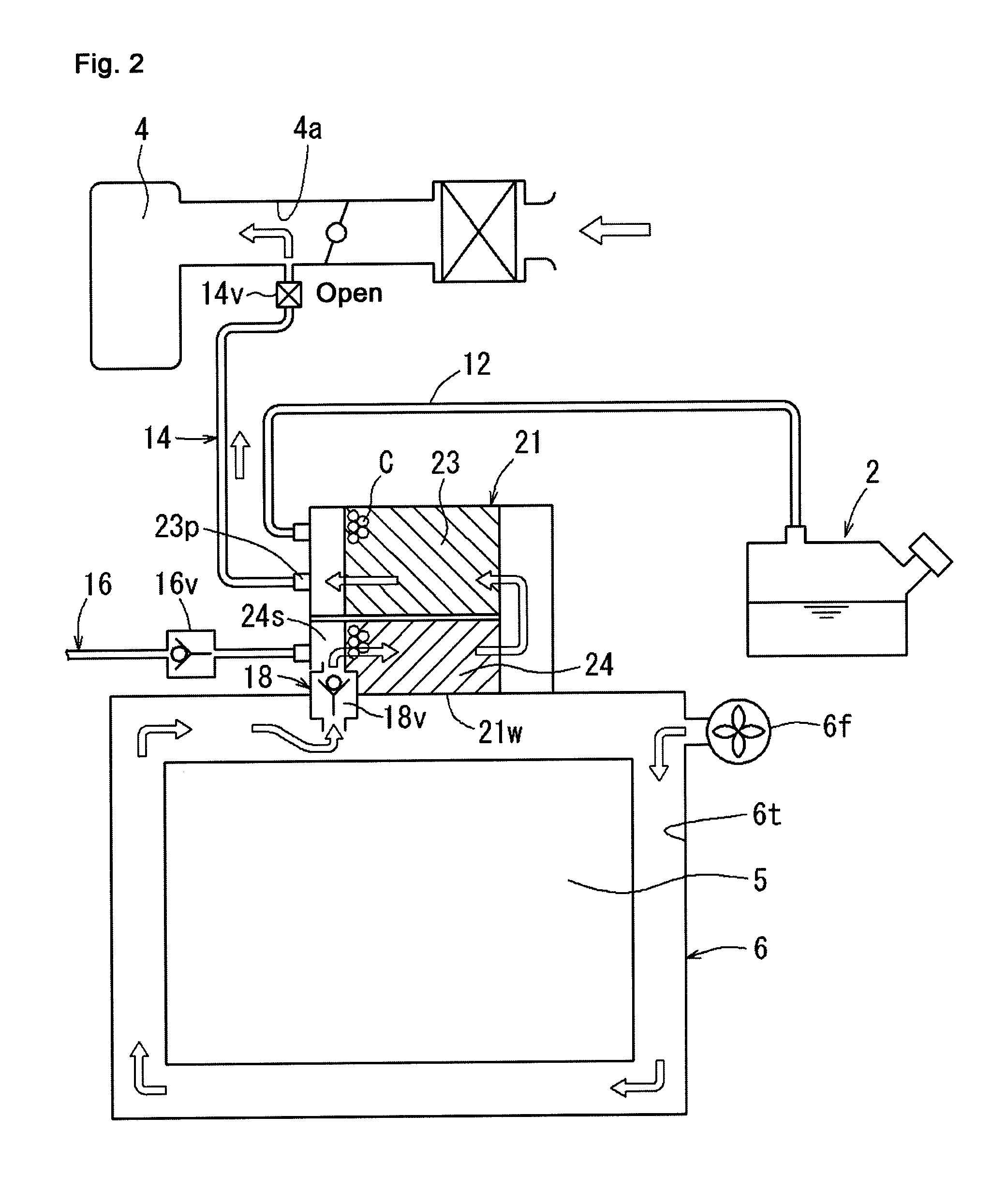
[0022]An evaporated fuel treatment apparatus according to a first embodiment of the present invention is described below with reference to FIGS. 1 to 3. The evaporated fuel treatment apparatus according to the present embodiment is mounted in a hybrid vehicle that has an engine and a motor as a drive source.
[0023]10>
An evaporated fuel treatment apparatus 10 has a canister 20, an evaporated fuel passage 12, a purge passage 14, an air passage 16, and a connecting passage 18. The canister 20 adsorbs vapor of fuel 2f (evaporated fuel) in a fuel tank 2. The evaporated fuel passage 12 directs the evaporated fuel in the fuel tank 2 to the canister 20. The purge passage 14 connects the canister 20 and an intake passage 4a of an engine 4. The air passage 16 emits air from the canister 20. The connecting passage 18 connects the canister 20 and a housing container 6 (battery container 6) of a battery 5.
[0024]20>
With reference to FIG. 1, the canister 20 has a hermetically-sealed canister contai...
second embodiment
[0033]An evaporated fuel treatment apparatus according to a second embodiment of the present invention is described below with reference to FIGS. 4 to 6. In the evaporated fuel treatment apparatus according to the present embodiment, the battery container 6 and the canister 20 of the evaporated fuel treatment apparatus 10 in the first embodiment are disposed separately. Accordingly, a configuration in which the adsorbent C in the canister 20 is heated by the heat of the battery 5 is different from that in the evaporated fuel treatment apparatus 10 of the first embodiment. Configurations other than the above are similar in the evaporated fuel treatment apparatus 10 of the present embodiment and the evaporated fuel treatment apparatus 10 of the first embodiment. Thus, the configurations similar to those of the evaporated fuel treatment apparatus 10 of the first embodiment are denoted with the same reference numerals and their explanations are omitted.
[0034]In the battery container 6 o...
PUM
 Abstract
Description
Claims
Application Information