Thermal protection circuit for an LED bulb

a technology of led bulbs and thermal protection circuits, which is applied in emergency protective arrangements, emergency protection arrangements for limiting excess voltage/current, and coupling device connections. it can solve problems such as failure of led bulbs, affecting the amount of heat produced by led bulbs, and reducing the operating life of led bulbs

Inactive Publication Date: 2011-12-08
SWITCH BULB CO INC
View PDF8 Cites 46 Cited by
  • Summary
  • Abstract
  • Description
  • Claims
  • Application Information

AI Technical Summary

Problems solved by technology

High temperatures may reduce the operating life of an LED bulb.
Failure in any one of these components may result in failure of the LED bulb.
Therefore, the number and type of LEDs present in the bulb may affect the amount of heat the LED bulb produces.
Additionally, drive circuitry may also produce significant amounts of heat.
However, the additional circuitry required for this task must fit, along with the other required components, within the limited form factor of the LED bulb.
LED bulbs meant as replacements for common lamp bulbs in other countries are also limited to comparable volumes.
The limited space in LED bulbs with common bulb form factors prohibits the use of a conventional thermal protection circuit used in microelectronics.
However, the addition of these components to the LED bulb is difficult due to the limited space of common bulb form factors.

Method used


Image

  • Thermal protection circuit for an LED bulb
  • Thermal protection circuit for an LED bulb
  • Thermal protection circuit for an LED bulb

Examples


Embodiment Construction

[0018]The following description is presented to enable a person of ordinary skill in the art to make and use the various embodiments. Descriptions of specific devices, techniques, and applications are provided only as examples. Various modifications to the examples described herein will be readily apparent to those of ordinary skill in the art, and the general principles defined herein may be applied to other examples and applications without departing from the spirit and scope of the various embodiments. Thus, the various embodiments are not intended to be limited to the examples described herein and shown, but are to be accorded the scope consistent with the claims.

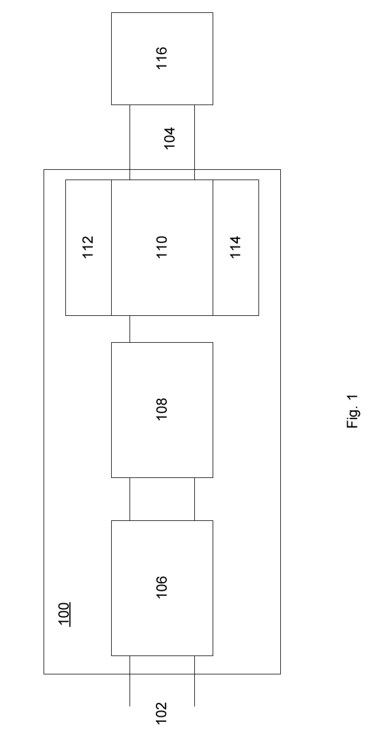
[0019]FIG. 1 depicts a functional level diagram of exemplary driver circuit 100 utilizing a thermal shutdown circuit. Driver circuit 100 may be used in an LED bulb to power one or more LEDs 116. As an input, driver circuit 100 takes an input line voltage (e.g., 120VAC, 60 Hz in the U.S.) at input 102. As an output, driv...


PUM


Abstract

A light-emitting diode (LED) bulb has an LED within a shell. The LED bulb also includes a driver circuit for providing current to the LED. The drive circuit has a thermal protection circuit, which includes a thermistor having a positive thermal coefficient and a switching temperature. The driver circuit also includes a switch-mode power supply (SMPS) controller with an input pin and an output pin. The thermistor is connected to the input pin. When the thermistor temperature is above the switching temperature, the thermal protection circuit causes the SMPS controller to produce a signal with a second duty cycle on the output pin. When the thermistor temperature is below the switching temperature, the thermal protection circuit causes the SMPS controller to produce a signal with a first duty cycle on the output pin. The second duty cycle is higher than the first duty cycle.

Description

BACKGROUND[0001]1. Field[0002]The present disclosure generally relates to a driver circuit for light-emitting diode (LED) bulbs, and, more particularly, to a driver circuit with thermal protection circuitry for preventing damage to an LED bulb that may result from overheating.[0003]2. Description of the Related Art[0004]High temperatures may reduce the operating life of an LED bulb. The LEDs, the driver circuitry, and the cooling system may all be sensitive to heat build-up in the LED bulb. Failure in any one of these components may result in failure of the LED bulb.[0005]The operating temperature of an LED bulb depends on many factors. For example, each individual LED produces heat. Therefore, the number and type of LEDs present in the bulb may affect the amount of heat the LED bulb produces. Additionally, drive circuitry may also produce significant amounts of heat.[0006]Other factors may determine the rate at which generated heat is dissipated. For example, the nature of the encl...

Claims


Application Information

Patent Timeline
Patent Type & Authority Applications(United States)
IPC IPC(8): H05B37/02H05B44/00
CPCY02B20/341H05B33/0815F21V29/70F21K9/232H05B45/56H05B45/18Y02B20/30H05B45/375
Inventor LENK, RONALD J.GRAINGER, JOHN D.
Owner SWITCH BULB CO INC
Why Eureka
Try Eureka