
Deformation measuring apparatus and deformation measuring method

a deformation measurement and measurement method technology, applied in the direction of interferometers, force measurement by measuring optical property variation, instruments, etc., can solve the problem of blurred fringes, inability to identify, and spatial frequency of fringes which can be captured by the camera

Inactive Publication Date: 2011-12-08
CANON KK
View PDF2 Cites 12 Cited by
  • Summary
  • Abstract
  • Description
  • Claims
  • Application Information

AI Technical Summary

Problems solved by technology

However, as the amount of deformation becomes larger and the number of fringes increases, spatial frequencies of fringes which can be captured by the camera 8 have an upper limit, and thus the fringes are blurred to become unidentifiable.

Method used


Image

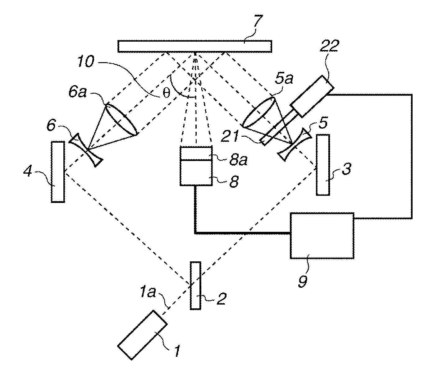
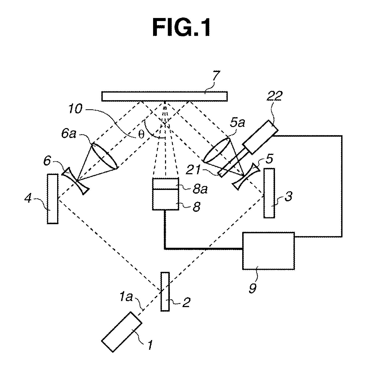
  • Deformation measuring apparatus and deformation measuring method
  • Deformation measuring apparatus and deformation measuring method
  • Deformation measuring apparatus and deformation measuring method

Examples


experimental example

[0093]Using the apparatus according to the first exemplary embodiment, the amount of deformation is measured by subjecting a metal piece processed to a shape of dumbbell test specimen to stretched deformation by a tensile testing machine.

[0094]As a sample, a plate made of SUS304 with the thickness of 0.01 mm which has been processed to a shape of No. 1 dumbbell (JIS standards) (see FIG. 8). The above-described sample was attached on the tensile testing machine, and the speckle interference patterns were acquired at intervals of 0.5 sec, while pulling the sample at a tensile speed of 10 μm / s.

[0095]The sample was placed so that the incident angles of two laser beams into the sample each become 45° and −45° from the normal line, within a plane composed of an axis parallel to pulling direction and passing through a center of the sample, and the normal line of the center of the sample.

[0096]The tilt angle of the gonio-stage is set to 5°, and the sample was repetitively tilted in opposite...


PUM


Abstract

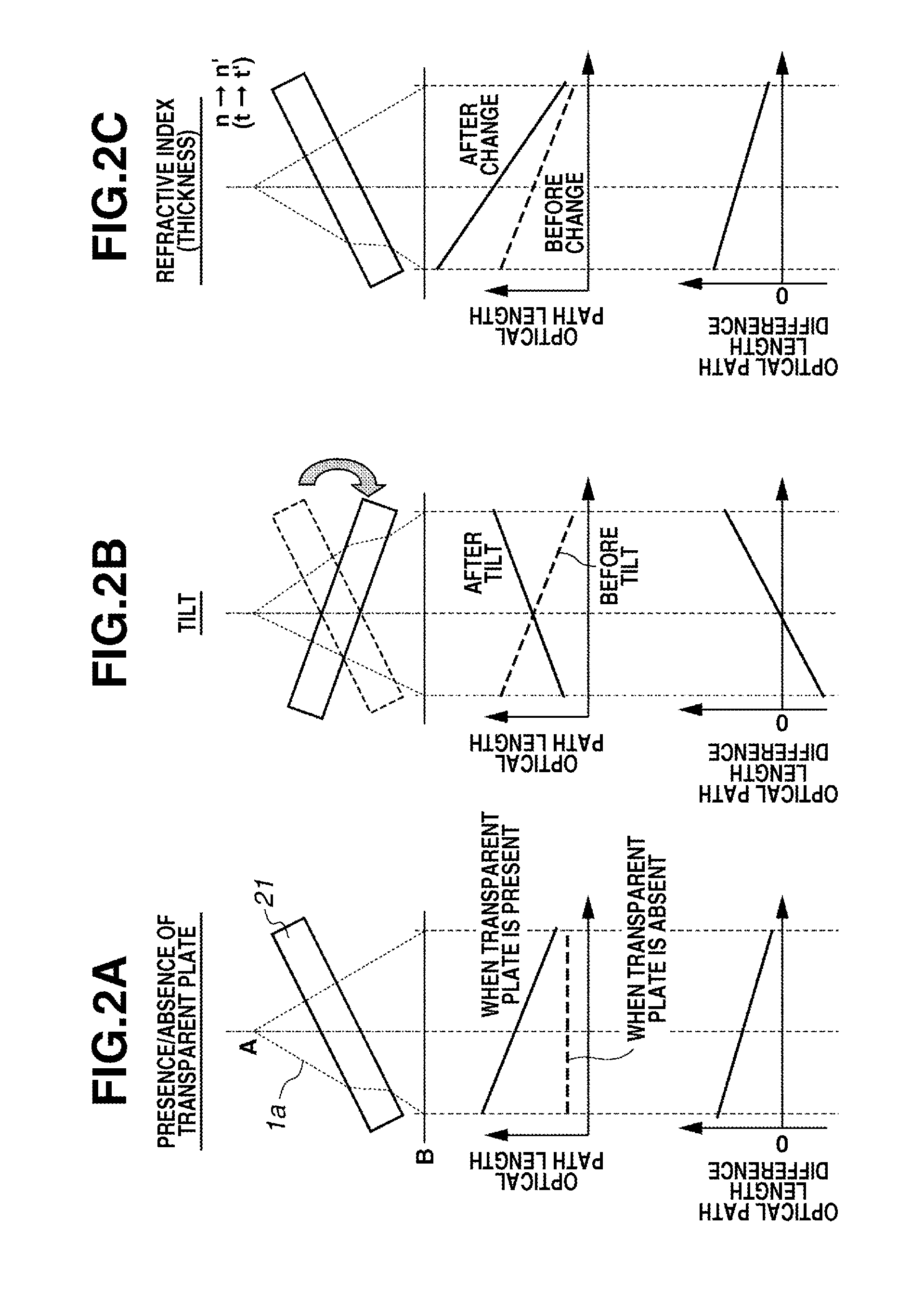
An apparatus and a method capable of measuring large deformation with a high accuracy and dynamically, using speckle interference, utilizes an optical path where one laser beam out of two laser beams becomes non-collimated light and a plane parallel transparent plate, and can form carrier fringes. More specifically, the transparent plate is arranged on the optical path where the non-collimated light is formed, or is removed from the optical path, or a refractive index, or a thickness of the transparent plate arranged on the optical path, or a tilt angle relative to an optical axis is changed. The phase analysis can be performed from fringe images corresponding to the deformation, by performing repetitively the above-described processing and acquisition of the speckle interference pattern.

Description

BACKGROUND OF THE INVENTION[0001]1. Field of the Invention[0002]The present invention relates to a method for measuring an amount of deformation of an object, and more particularly, to a method for measuring, in a non-contact manner, the deformation of an industrial product caused by being pressed.[0003]2. Description of the Related Art[0004]A speckle interference method is an optical measuring method utilizing a spot-shaped bright and dark pattern (speckle interference pattern) generated when a rough-surfaced object is irradiated with a laser beam. Since the speckle interference pattern is an inherent pattern corresponding to a surface shape of an object to be measured which has been irradiated with a laser beam, the amount of deformation of the observed surface can be estimated from the change thereof.[0005]First, two laser beams are irradiated on the object to be measured, and respective scattering lights generated on the observed surface of the measured object are caused to inte...

Claims


Application Information

Patent Timeline
IPC IPC(8): G01L1/24
CPCG01B11/162G01B9/02095G01B9/02032G01B9/02084G01N2021/479G01B2290/35G01N21/45G01N21/4788G01B9/02096
Inventor SUGIMOTO, TAKASHI
Owner CANON KK
Learn More