Duplex optical connector unit

a duplex optical connector and unit technology, applied in the field of optical connectors, can solve the problems of increasing assembly man-hours and costs, increasing the size of the unit, and a large number of components, and achieve the effect of easy exchange of positions of optical connectors

Inactive Publication Date: 2011-12-08
SANCALL
View PDF5 Cites 88 Cited by
  • Summary
  • Abstract
  • Description
  • Claims
  • Application Information

AI Technical Summary

Benefits of technology

[0020]As described above, in contrast to an operation lever which has been provided in a holder in a conventional product, according to the present invention, the operation lever is provided in a boot, thereby being capable of easily exchanging positions of a pair of optical connectors. As a result, even when the pair of optical connectors are reversely mounted by mistake during assembly, the optical connectors can be exchanged back into correct positions in use, and hence the optical connector unit and a duplex cable can be used without waste.

Problems solved by technology

Further, the two boots 104a, 104b need to be provided for protecting the two bifurcated optical fiber cables 101a, 101b, resulting in increase in size of the unit, a large number of components, and increase in assembly man-hours and cost.
However, the duplex cable 101 has a flat spectacles-like cross-sectional shape as illustrated in FIG. 8, and hence it is difficult to smoothly twist the duplex cable 101 particularly when the duplex cable 101 is curved.
As a result, the optical connector unit 100 resists rotation, which leads to poor mounting workability.
However, it is difficult to tie the duplex cables 101 together due to its spectacles-like cross-sectional shape, and thus the arrangement of the wiring is difficult.
Moreover, not only is it difficult to rotate one duplex cable 101 having a spectacles-like cross-sectional shape, but also it becomes more difficult to rotate the plurality of duplex cables 101 tied together because the cables interfere with each other, which leads to poor wiring workability.

Method used


Image

  • Duplex optical connector unit
  • Duplex optical connector unit
  • Duplex optical connector unit

Examples


Embodiment Construction

[0044]Hereinafter, an embodiment of the present invention is described with reference to the drawings.

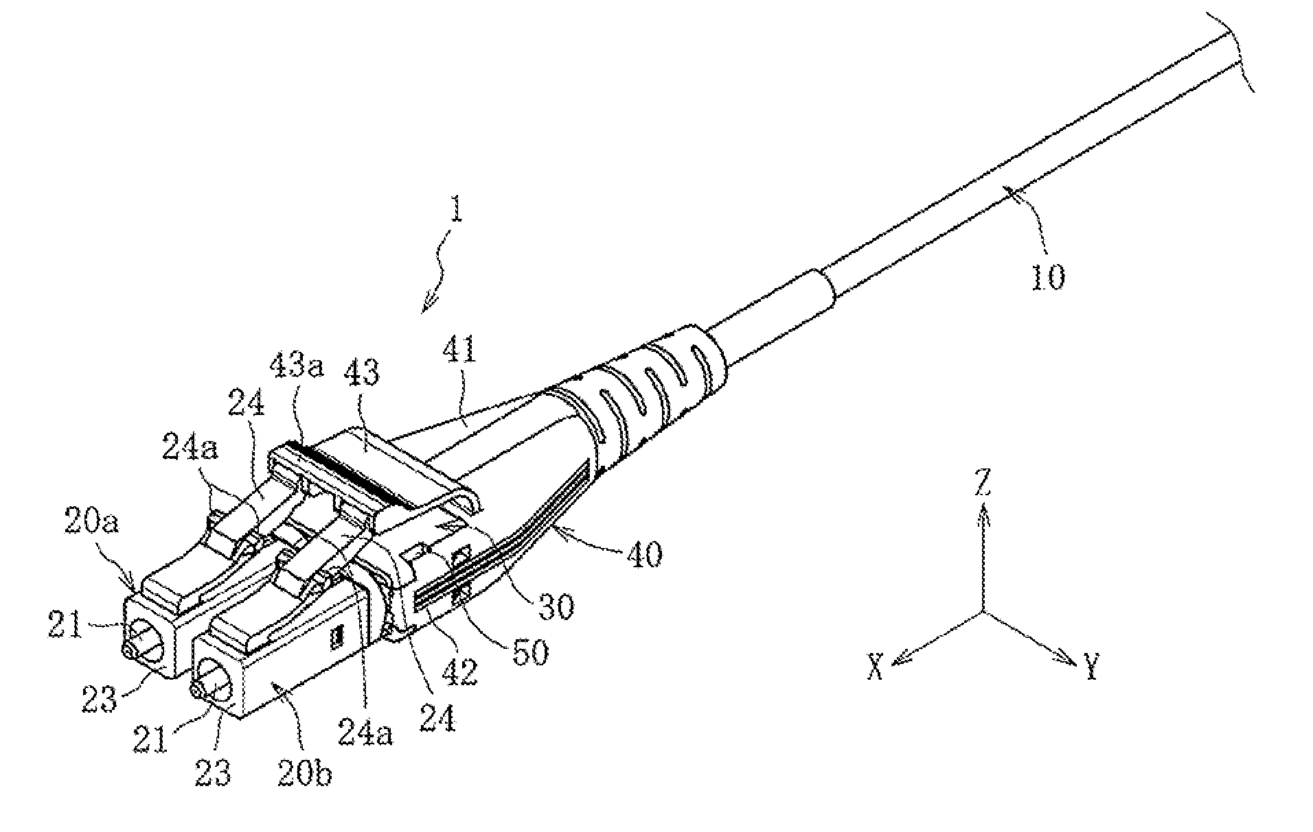
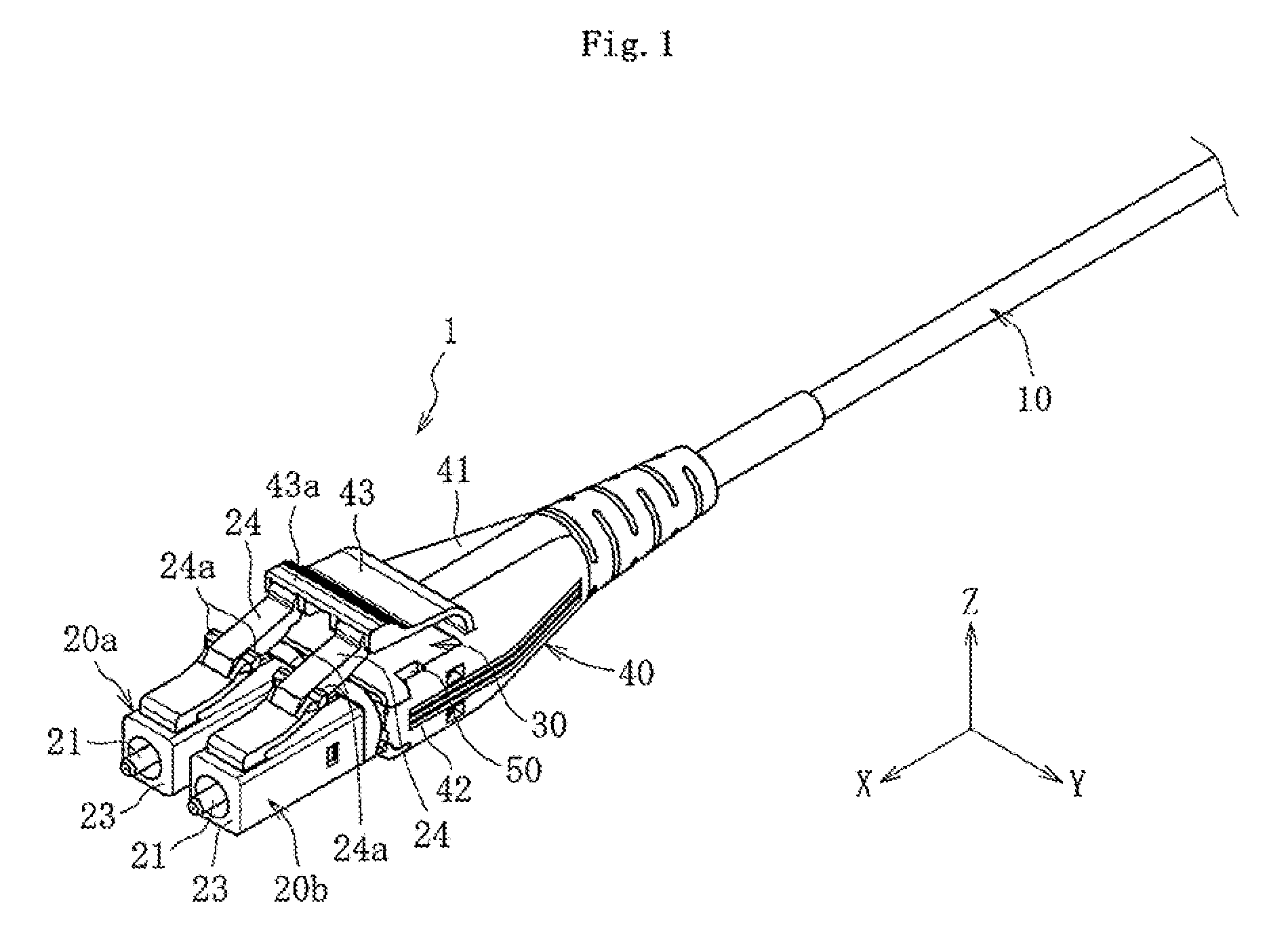
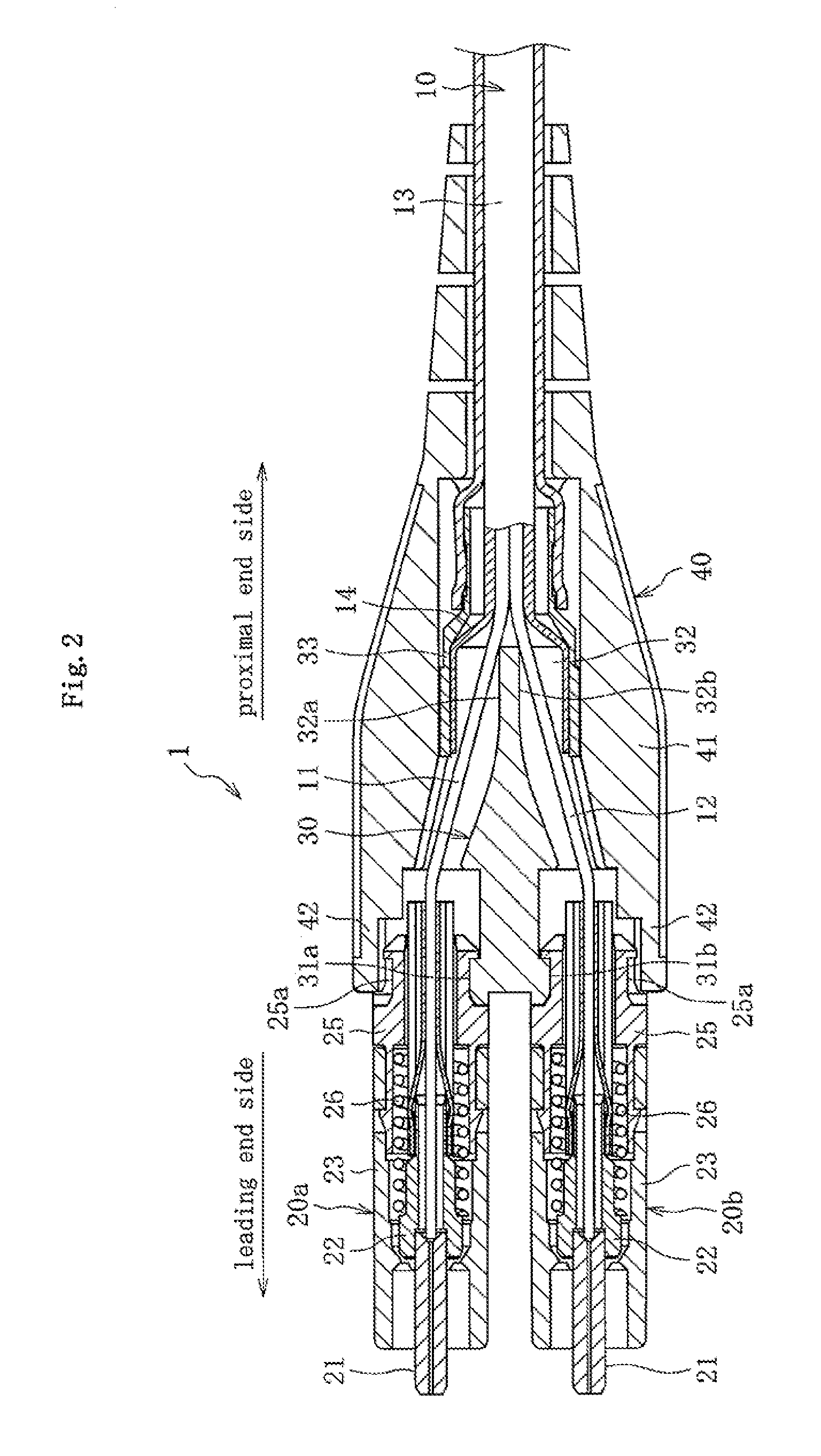
[0045]As illustrated in FIG. 1, an optical connector unit 1 according to the embodiment of the present invention is fixed to a leading end of a duplex cable 10. The duplex cable 10 includes a pair of optical fibers therein. In this embodiment, as illustrated in FIG. 2, the duplex cable 10 includes a pair of bare fibers 11, 12 incorporating the optical fibers, a covering tube 13 which covers outer peripheries of the pair of bare fibers 11, 12 so as to hold them together, and a reinforcement fiber 14 filled between the bare fibers 11, 12 and the covering tube 13. The duplex cable 10 has a substantially circular cross-sectional shape, similarly to the duplex cable 201 illustrated in FIG. 11.

[0046]The optical connector unit 1 is mounted into a mounting hole of an optical adapter (not shown). The optical connector unit 1 mainly includes an input optical connector 20a, an output optical c...


PUM


Abstract

Provided is a duplex optical connector unit, in which locking levers extending obliquely upward toward a proximal end side and including interlocking portions engaging with an optical adapter are provided on top surfaces of housings of optical connectors, and an operation lever extending obliquely upward toward a leading end side and including a pressing part located above the locking levers is provided in a top surface of a main body portion of a boot.

Description

TECHNICAL FIELD[0001]The present invention relates to an optical connector, and more particularly, to a duplex optical connector unit for bidirectional communication including a pair of optical connectors.BACKGROUND ART[0002]An optical connector is fixed to a leading end of an optical fiber, and is used for connecting the optical fiber to another optical fiber or an optical communication module via an optical adapter or an optical receptacle. A duplex optical connector unit for bidirectional communication including an input optical connector and an output optical connector (hereinafter, also simply referred to as “optical connector unit”) is known as a kind of optical connector (for example, see Patent Literature 1).[0003]As a cable for bidirectional communication, for example, as illustrated in FIG. 8, there is known a duplex cable 101 having a spectacles-like cross-sectional shape, which is formed by integrally joining two optical fiber cables 101a, 101b. The optical fiber cables ...

Claims


Application Information

Patent Timeline
Patent Type & Authority Applications(United States)
IPC IPC(8): G02B6/36
CPCG02B6/3825G02B6/3893G02B6/3887G02B6/3879G02B6/38875G02B6/3888
Inventor NAKAGAWA, MASAYA
Owner SANCALL
Why Eureka
Try Eureka