Thermal imaging camera with a fast electromechanical shutter device

a shutter device and thermal imaging technology, applied in the field of thermal imaging cameras with shutter devices, can solve the problems of high acceleration peaks, large vibration of shutter flags, and abrupt start and braking, and achieve the effects of improving the kinematics of shutter flags, low maximum electric power consumption of motors, and no high acceleration peaks

Active Publication Date: 2011-12-08
DRAGER SAFETY
View PDF4 Cites 9 Cited by
  • Summary
  • Abstract
  • Description
  • Claims
  • Application Information

AI Technical Summary

Benefits of technology

[0009]The object of the present invention is to provide a thermal imaging camera with an electromechanical shutter device with improved kinematics of the shutter flag, in which the shutter flag can be moved rapidly and without high ac

Problems solved by technology

This leads to high acceleration peaks at the beginning and at the end of the motion and consequently to abrupt start and braking and great vibrations of the shutter flag when the end positions are reached.
Another drawback of the shutter device shown in U.S. Pat. No. 7,484,885 B1 is that pronounced electric current peaks develop in the motor during start-up and braking, which makes use especially difficult in areas with exp

Method used


Image

  • Thermal imaging camera with a fast electromechanical shutter device
  • Thermal imaging camera with a fast electromechanical shutter device
  • Thermal imaging camera with a fast electromechanical shutter device

Examples


Embodiment Construction

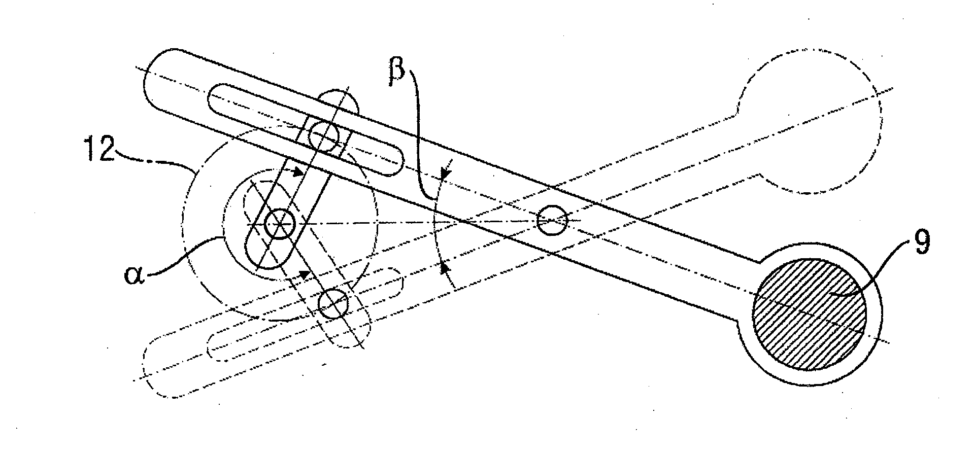
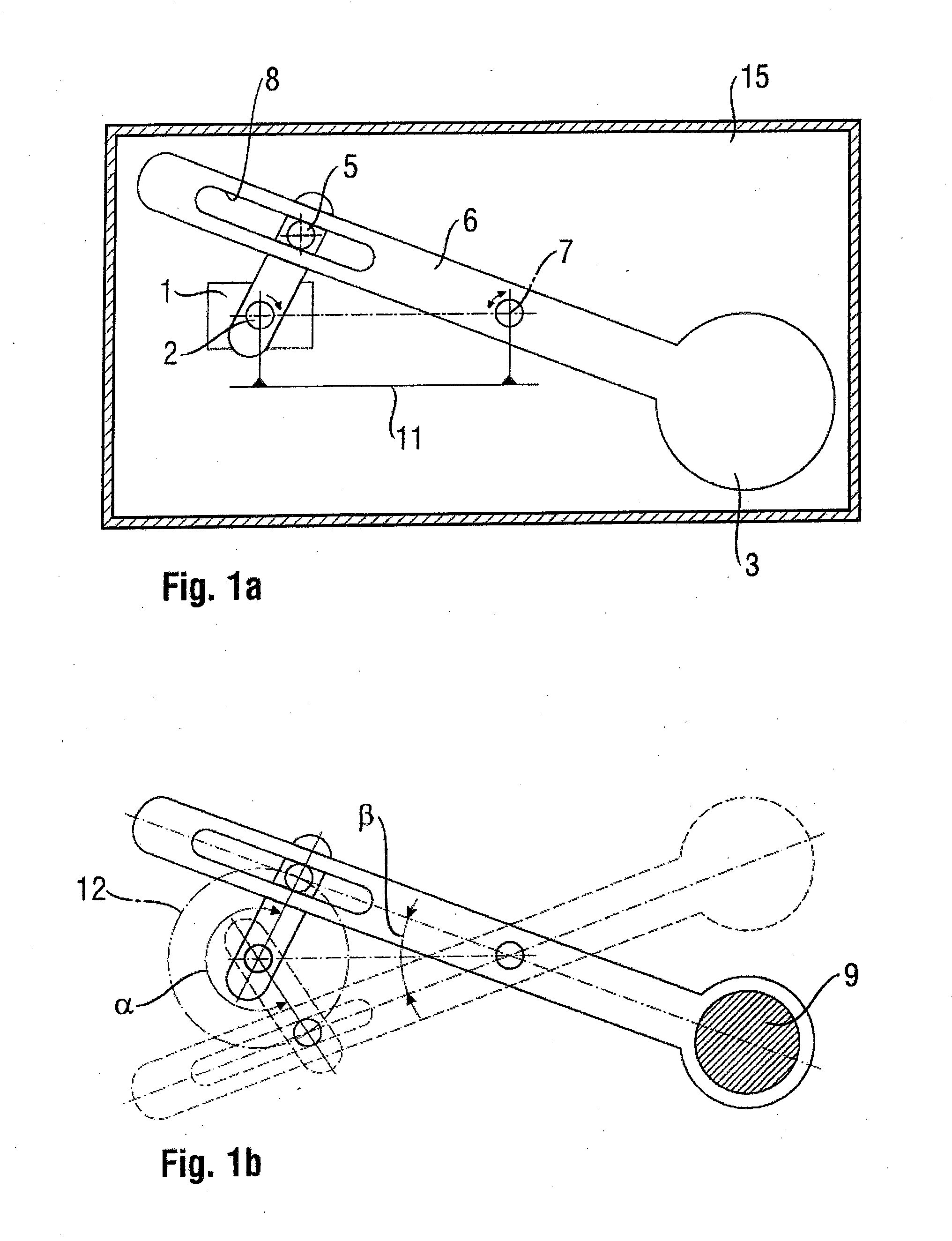
[0020]Referring to the drawings in particular, FIG. 1a shows a schematic arrangement of a thermal imaging camera (camera body) 15 according to the present invention, the view being limited to the features of the arrangement that are essential for the present invention, given by the electromechanical shutter device, for the sake of clarity.

[0021]The shutter device comprises essentially a motor 1 with a motor shaft 2 and a crank-and-rocker mechanism with rectilinear sliding joint.

[0022]The crank-and-rocker mechanism comprises a crank 4 and a rocker 6, with a shutter flag 3 being formed on said rocker 6.

[0023]Crank 4 is seated on the motor shaft 2 and may be both a connecting rod with a crank pin 5 formed at the free end thereof or a crank disk with an eccentrically arranged crank pin 5.

[0024]Rocker 6 is mounted rotatably on a pivot axis 7, which is arranged at a fixed distance from the motor shaft 2 via a frame 11 and is directed in parallel to the motor shaft 2 and encloses, via an e...


PUM


Abstract

A thermal imaging camera, with an electromechanical shutter device for interrupting the ray path from time to time, has a motor (1), a motor shaft (2) and a shutter flag (3). The motor shaft (2) and the shutter flag (3) are in connection with one another via a crank-and-rocker mechanism. The crank-and-rocker mechanism includes a crank (4) rotatable about the motor shaft (2) with a crank pin (5) and with a rocker (6), at one end of which an elongated hole (8) is provided, which forms a rectilinear sliding joint together with the crank pin (5), and at the other end of which the shutter flag (3) is formed.

Description

CROSS REFERENCE TO RELATED APPLICATIONS[0001]This application claims the benefit of priority under 35 U.S.C. §119 of German Patent DE 10 2010 023 167.3 filed Jun. 7, 2010, the entire contents of which are incorporated herein by reference.FIELD OF THE INVENTION[0002]The present invention pertains to a thermal imaging camera with a shutter device.BACKGROUND OF THE INVENTION[0003]A thermal imaging camera with a shutter device is known from U.S. Pat. No. 7,484,885 B1.[0004]It is common in thermal imaging cameras to briefly introduce a surface of a homogeneous temperature, which completely interrupts the ray path, into the ray path at regular intervals for image correction. Electromechanical shutter devices, which make possible a change in state between fully interrupted and fully open ray path especially extremely rapidly, are used for this.[0005]A thermal imaging camera with an electromechanical shutter device, with which a shutter flag is pivoted into the ray path in order to make a t...

Claims


Application Information

Patent Timeline
IPC IPC(8): G03B9/08
CPCH04N5/2254H04N23/55G01J5/08G03B9/08H04N5/33G01J5/53
Inventor WEISBACH, FRANKSCHWARZER, BERND
Owner DRAGER SAFETY
Why Eureka
Try Eureka