Valve

a valve and plunger technology, applied in the field of valves, can solve the problems of reducing service life, generating unsatisfactory transverse forces, and reducing the service life, so as to reduce the assembly and the required structural space, and effectively prevent the tilting of the valve plunger

Active Publication Date: 2018-12-27
VITESCO TECH GERMANY GMBH
View PDF8 Cites 0 Cited by
  • Summary
  • Abstract
  • Description
  • Claims
  • Application Information

AI Technical Summary

Benefits of technology

[0015]It is furthermore advantageous if the valve plunger is supported with respect to a spatially fixed structure surrounding the valve by exactly one radial bearing. The use of only one radial bearing, for example a sliding sleeve, is particularly advantageous because, in this way, the construction of the valve is simplified and thus the assembly and the required structural space are reduced. In an alternative embodiment, it is also possible for multiple radial bearings to be provided which, in an axial direction, each have a shorter extent than the single radial bearing. In the case of multiple short radial bearings, the radial bearings are preferably arranged in the immediate vicinity of the end regions of the valve plunger in order to effectively prevent tilting of the valve plunger.
[0016]It is furthermore advantageous if the thrust rods are rigidly connected to one another such that movement coupling is realized between two thrust rods. This is advantageous in order to achieve altogether greater stability in the valve, and in particular to avoid relative rotations and tilting. In particular, the kinematics of the valve are considerably improved in this way. The two thrust rods may, for example, be welded, to one another or rigidly connected to one another by another coupling element that does not restrict the free movement of the valve plunger.
[0017]It is also expedient for the rocker arm to form, together with the thrust rods and the valve plunger, a knee lever joint. A knee lever joint forms a particularly robust and stable joint, which is advantageous in particular for the transmission of relatively small movements. The maximum possible movement by the knee lever joint can be influenced in particular by the arrangement of the axis of rotation of the rocker arm and the connection of the thrust rods to the rocker arm in relation to the axis of rotation.
[0018]It is furthermore advantageous if the thrust rods have apertures through which the valve plunger arranged between the thrust rods is accessible. The apertures are formed in particular by punched-out portions in the thrust rods. These apertures advantageously permit access to the valve plunger arranged between the thrust rods. This is advantageous in particular for assembly purposes because, for example, the connection between the springe and the plate-like elements of the valve plunger can be produced more easily.
[0019]The apertures are furthermore advantageous for also permitting the use of particularly long valve plungers. Through the use of long valve plungers, the acting transverse forces can be further reduced. To be able to use as long a valve plunger as possible despite the normally very restricted structural space, it is advantageous if the valve plunger can also be accessed through the thrust rods. This in particular considerably simplifies the assembly process.

Problems solved by technology

A disadvantage of devices of this type is in particular that, during the conversion of the movement, undesired transverse forces are generated, which can be transmitted to the valve plunger or to the valve disk.
This leads to greater wear and to a reduced service life.
It is furthermore a disadvantage that, in particular slots in slotted-link mechanisms have to be produced with vary high production accuracy in order to minimize the play at the valve disk and the valve plunger.
It is also a disadvantage that, owing to installation space requirements and the structural design of crank drives or slotted-link drives, it is often the case that only one-sided mounting of the valve plunger or of the kinematic mechanism for converting the movement is provided, which can result in particular in tilting or jamming of the valve plunger.

Method used


Image

  • Valve
  • Valve
  • Valve

Examples


Embodiment Construction

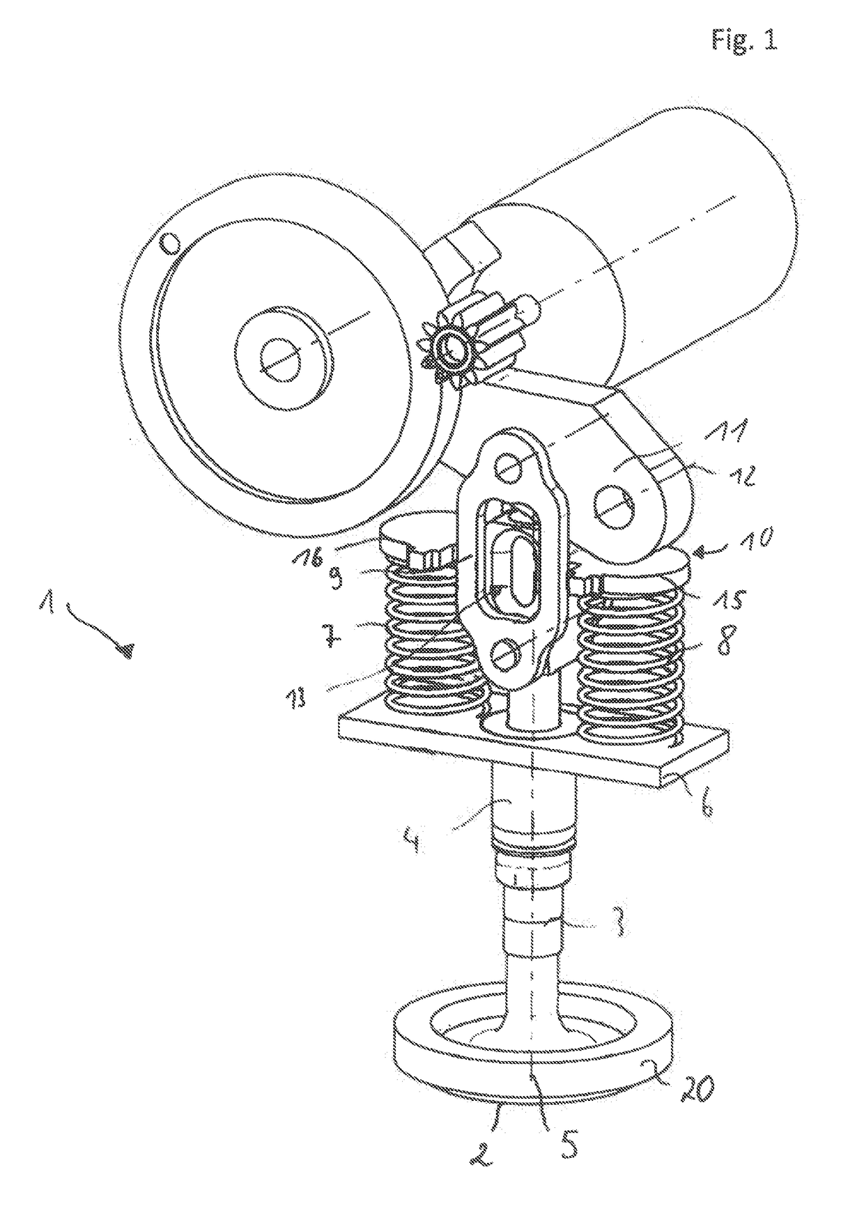
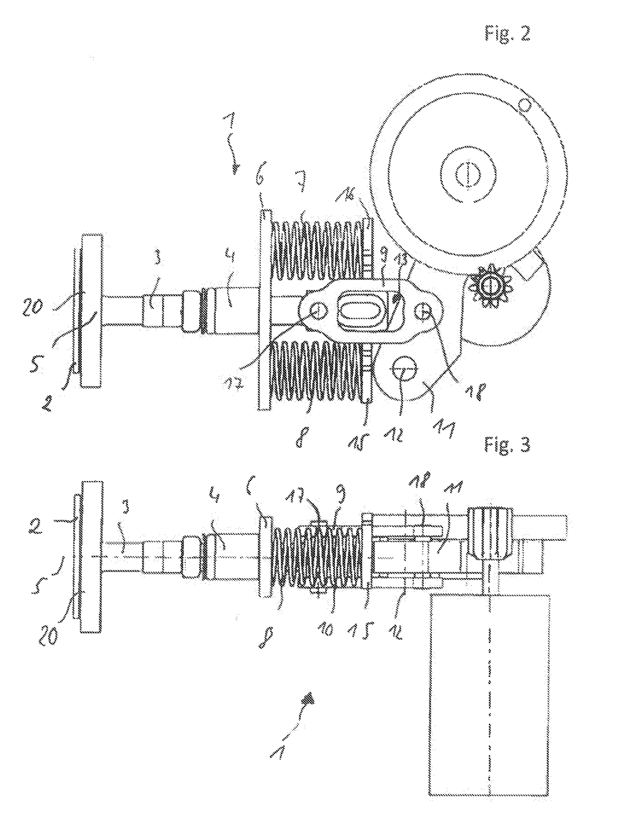
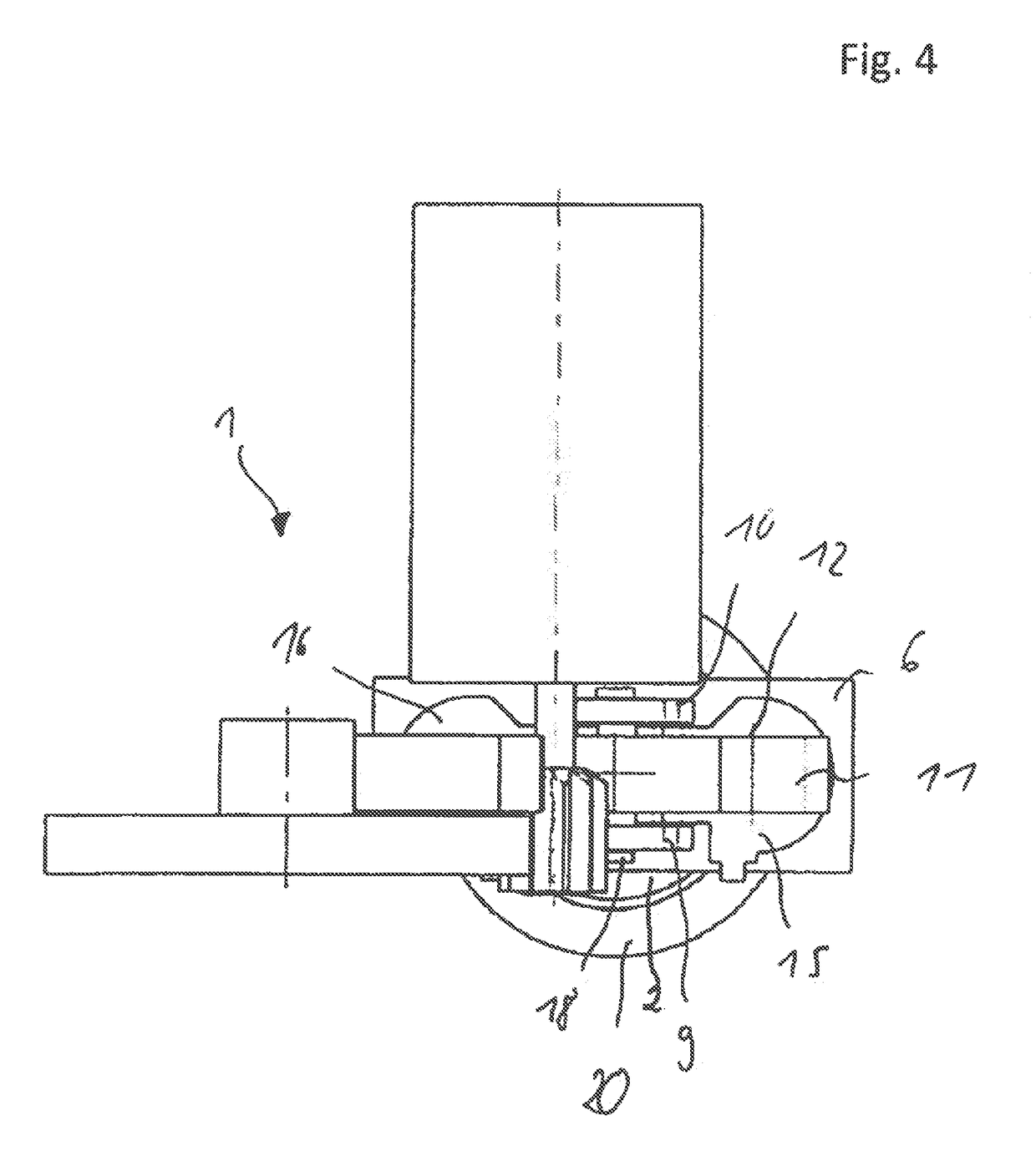
[0028]FIG. 1 shows a perspective view of a valve 1. The valve 1 has a valve disk 2 which is rigidly connected to a valve plunger 3. The valve plunger 3 is mounted so as to be movable along an axis 5 by a radial hearing 4 which is formed by a sleeve. The axis 5 also corresponds to the central axis 5 of the valve plunger 3, The valve disk 2 can be moved along the central axis 5 of the valve plunger 3, whereby the valve disk can be moved into a valve seat 20 or out of the valve seat 20. In this way, a flow path can be opened or closed. The valve seat 20 is indicated in FIGS. 1 to 4 as a ring-shaped element and is preferably part of a housing (the rest of which is not shown) which delimits, for example, a flow duct.

[0029]The plate element 6 is illustrated representatively as a spatially fixed structure, for example a housing. The valve 1 can be advantageously integrated into this spatially fixed structure, and in particular, the illustrated springs 7, 8 can be supported relative to the ...


PUM


Abstract

A valve for opening or closing a flow section has: a valve disk, a valve plunger and a transmission for converting rotary motion into translational motion. The transmission has a rocker arm mounted to rotate about an axis of relation, the rocker arm is linked to the valve plunger by connecting rods, and the connecting rods are mounted to rotate relative to the rocker arm and the valve plunger. A restoring device generates a force component to counteract a movement of the valve plunger transmitted to the valve plunger by the rocker arm and the connecting rods.

Description

CROSS-REFERENCE TO RELATED APPLICATIONS[0001]This is a U.S. national stage of application No. PCT / EP2016 / 079774filed on 5 Dec. 2015, which claims priority to the Germany Application No. 10 2015 224 466.0 filed 7 Dec. 2015, the content of both incorporated herein by reference.BACKGROUND OF THE INVENTION1. Field of the Invention[0002]The invention relates to a valve for opening or closing a flow path.2. Related Art[0003]In numerous application areas, rotational movements of a drive motor are converted into a linear or a translational movement for the purposes of actuating a valve. This principle is also applied, for example, in valves for controlling exhaust-gas recirculation in motor vehicles. For this purpose, use is often made of a gear transmission that converts the rotational movement into a linear or translational movement by a corresponding kinematic mechanism. The conversion of the rotational movement may be realized, for example, by a crank drive or a slotted-link mechanism. ...

Claims


Application Information

Patent Timeline
Patent Type & Authority Applications(United States)
IPC IPC(8): F02M26/67F16K31/04F16K31/52F02M26/54
CPCF02M26/67F16K31/047F16K31/52F02M26/54F16K31/54
Inventor WEIS, CHRISTIANMIKOLAJEK, CARSTEN
Owner VITESCO TECH GERMANY GMBH
Why Eureka
Try Eureka