Robotic apparatus for a compact painting booth

a compact, painting booth technology, applied in the direction of manipulators, spray booths, movable spraying apparatus, etc., can solve the problems of increasing the size and weight of the robot arms, reducing the flexibility of the near reach, and reducing the efficiency of the painter. , to achieve the effect of minimizing paint waste and wait time, improving kinematics, and improving flexibility

Active Publication Date: 2021-11-02
FANUC ROBOTICS NORTH AMERICA
View PDF37 Cites 0 Cited by
  • Summary
  • Abstract
  • Description
  • Claims
  • Application Information

AI Technical Summary

Benefits of technology

[0010]In accordance with the teachings of the present disclosure, a Next Generation Painting Robot with advanced fluid delivery system design, enhanced kinematics and a service airlock compartment is disclosed. The disclosed painting robot includes a fluid delivery system which places color changing valves, cleaning valves and pumping hardware on the back side of the robot's mounting pedestal, where it can be serviced without a technician having to enter the spray booth. The fluid delivery system also allows much smaller and lighter robot arms, and is designed to minimize paint waste and wait time during color changes. The disclosed robot also includes a joint providing redundant inner arm rotation which, combined with the elimination of the color changing and fluid delivery equipment from the robot arms, enables dramatically improved near reach flexibility, which in turn allows a smaller spray booth. The disclosed improved robot painting system provides the ability for routine cleaning and maintenance to be performed without personnel entering the working area of the spray booth and without stopping painting operations, due to simplified outer arm design, remotely mounted fluid delivery equipment and a specially configured airlock booth adjacent to the robot pedestal offering complete serviceability of the entire outer arm of the robot, wrist and applicator.

Problems solved by technology

The stopping period can be as much as thirty minutes every four hours, which is very costly.
However, under the ever-present pressure to improve efficiency and reduce cost and waste, several aspects of present painting robots have been identified as being less than optimal.
As discussed above, paint line downtime is expensive and to be avoided whenever possible.
Furthermore, the traditional placement of the fluid delivery equipment on the outer arm increases the size and weight of the robot arms dramatically, because hoses and fittings for every color must be routed along the entire length of the arms, and the fluid delivery equipment itself adds a lot of size and weight to the outer arm.
Another limitation of current painting robots is that they are limited in reach and flexibility due to the placement of the fluid delivery equipment on the moving robot arm along with routing a multitude of paint and control lines to the color changing and fluid pumping equipment.
This configuration severely limits flexibility—especially near reach, where the robot is painting close to its mounting point and the arms are folded tightly.
A robot's lack of near reach flexibility causes paint spray booths to be designed with a greater clearance than desirable between the vehicles and the spray booth wall, which increases the volume of the spray booth and therefore the cost to environmentally control it.
The lack of near reach flexibility also means that the downline distance from one robot to the next is larger than desired, which increases the length and therefore the volume of the spray booth.
Furthermore, lack of flexibility means that an individual robot may not be able to paint all of the interior and exterior surfaces on one side of the vehicle, which then requires more robots to be installed on the paint line.
Yet another limitation of current painting robots is that the painting operation must be shut down periodically in order to perform cleaning and maintenance on the robots.
Painting robot arms are subject to the inevitable accumulation of paint overspray—especially the parts of the arm nearest the spraying of paint, which are the paint applicator itself and the outer arm near the applicator.
These cleaning time periods represent paint line down time, and are very costly.

Method used


Image

  • Robotic apparatus for a compact painting booth
  • Robotic apparatus for a compact painting booth
  • Robotic apparatus for a compact painting booth

Examples


Embodiment Construction

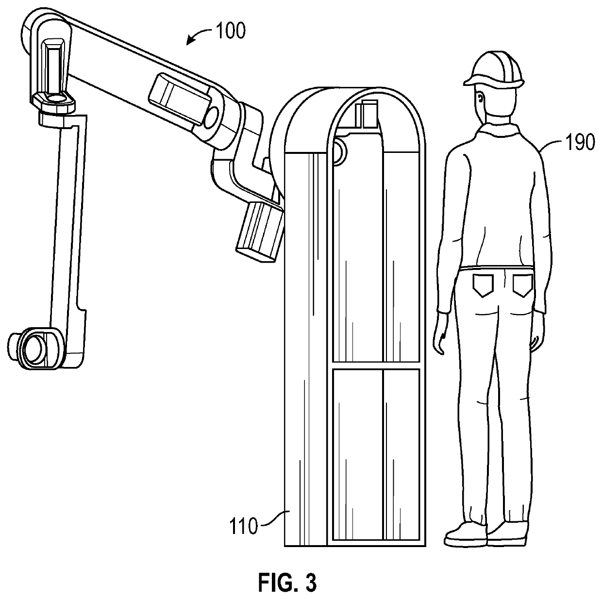
[0029]The following discussion of the embodiments of the disclosure directed to a Next Generation Painting Robot is merely exemplary in nature, and is in no way intended to limit the disclosed devices or their applications or uses. For example, the painting robot is described in the context of painting vehicles on a conveyor line, but the robot is anticipated to find applications painting or processing other types of objects. In respect of the methods disclosed, the steps presented are exemplary in nature, and thus, steps may be added, removed or reordered without departing from the spirit and scope of the invention.

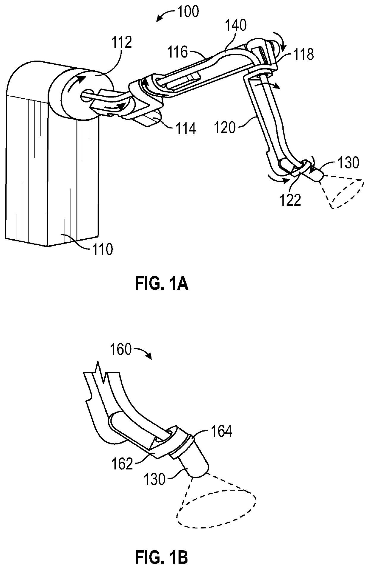
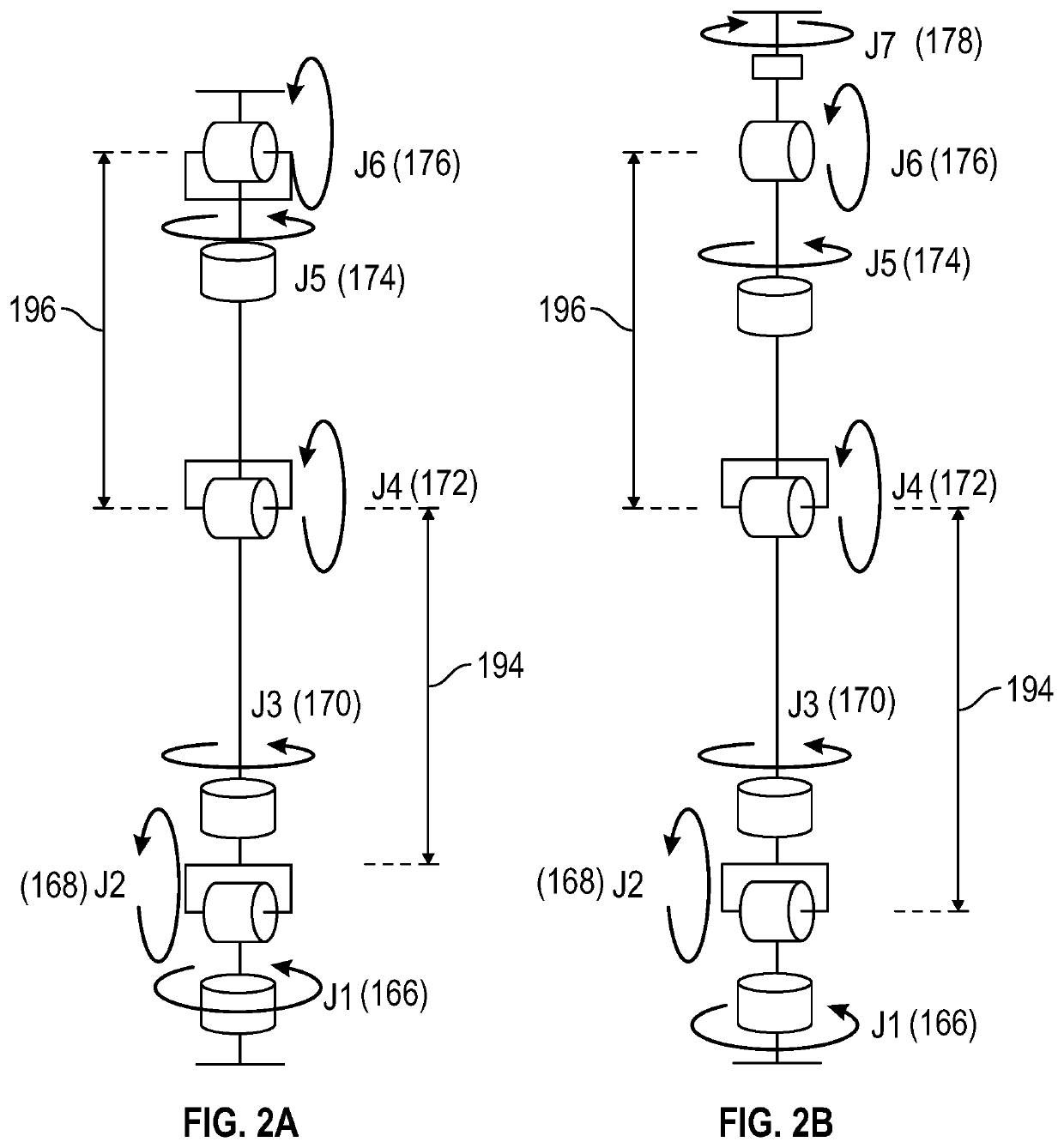
[0030]In order to address the shortcomings of the existing painting robots discussed above, an all-new robot has been designed with features including: improved painting efficiency; reduced installed cost per arm; reduced spray booth down time due to robot service and cleaning; increased robot uptime / availability; reduced color change waste; different inner and outer arm...


PUM


Abstract

A next generation painting robot with advanced fluid delivery system, enhanced kinematics and a service airlock compartment. The painting robot includes a fluid delivery system which places color changing valves and pumping hardware on the back side of the robot's mounting pedestal, where it can be serviced without a technician having to enter the spray booth. The fluid delivery system also allows smaller and lighter robot arms, and is designed to minimize paint waste and wait time during color changes. The robot also features kinematics providing redundant inner arm rotation. The arm kinematics, along with the smaller arms, a paint supply line routed through the center of first and third arm joints, and optimized motor conductor routing, dramatically improve near reach flexibility. The improved near reach flexibility in turn allows a smaller spray booth than possible with previous robot architectures.

Description

CROSS-REFERENCE TO RELATED APPLICATIONS[0001]This application claims the benefit of the priority date of U.S. Provisional Patent Application Ser. No. 62 / 666,134, titled NEXT GENERATION PAINTING ROBOT, filed May 3, 2018.BACKGROUNDField[0002]The present disclosure relates generally to the field of robotic painting equipment and, more particularly, to an improved robotic system used for painting automobile bodies or automotive component parts. The improvements are offered to meet the modern needs of paint shops that run continuously without interrupting the painting process for equipment maintenance or equipment cleaning. The fluid delivery system includes valves, pumps, and fluid lines which are presented to minimize color change time and paint waste while being mounted outside the spray booth where they can be serviced without stopping painting operations. Enhanced robot kinematics having improved flexibility and reach enables a smaller spray booth footprint and a shortened paint lin...

Claims


Application Information

Patent Timeline
Patent Type & Authority Patents(United States)
IPC IPC(8): B05B13/04B05B12/00B05B14/40B05B16/60B05B15/55B05B16/00B05B5/03B25J11/00B05B16/40B05B13/02B25J19/00B25J21/00
CPCB05B13/0431B05B5/03B05B12/00B05B13/0278B05B13/0452B05B14/40B05B15/55B05B16/40B05B16/60B05B16/90B05B16/95B25J11/0075B25J19/0066B25J19/0075B25J21/00B05B3/1014B05B12/14B05B9/0423
Inventor CLIFFORD, SCOTT J.MCCLOSKY, STAN H.CARBERY, DAVID A.
Owner FANUC ROBOTICS NORTH AMERICA
Why Eureka
Try Eureka