Ultrasonic endoscope

Active Publication Date: 2011-12-08
FUJIFILM CORP
View PDF12 Cites 6 Cited by
  • Summary
  • Abstract
  • Description
  • Claims
  • Application Information

AI Technical Summary

Benefits of technology

[0009]A connection pipe which constitutes the treatment tool insertion channel is arranged on the main body operating part side (hereinafter referred to as the proximal side) of the observation unit. Thus, when the observation unit is moved to the proximal side along the mounting hole, there is a concern that the observation unit may interfere with the connection pipe made of a bending pipe. Accordingly, when the observation unit is separated from the distal end body, in order to keep the connection pipe from becoming a hindrance, it is necessary to space the connection pipe apart from the observation unit, or shorten the length by which the lens barrel is held by the mounting hole. However, when the distance between the observation unit and the connection pipe is lengthened, the distal portion in the insertion part lengthens by an equivalent amount, and when the length of the lens barrel held by the mounting hole is shortened, the stability of holding of the observation unit deteriorates. Additionally, in a direct-viewing-type endoscope which does not include the ultrasonic observation mechanism, when the observation unit interferes with the connection pipe, the observation unit may not be pulled out straight to the proximal side.
[0011]The present invention has been made in view of the above points, and the object thereof is to provide an observation unit which can be stably held in a state where the observation unit is mounted on the distal portion, and can be easily removed without interfering with a connection pipe.

Problems solved by technology

Thus, when the observation unit is moved to the proximal side along the mounting hole, there is a concern that the observation unit may interfere with the connection pipe made of a bending pipe.
However, when the distance between the observation unit and the connection pipe is lengthened, the distal portion in the insertion part lengthens by an equivalent amount, and when the length of the lens barrel held by the mounting hole is shortened, the stability of holding of the observation unit deteriorates.
Additionally, in a direct-viewing-type endoscope which does not include the ultrasonic observation mechanism, when the observation unit interferes with the connection pipe, the observation unit may not be pulled out straight to the proximal side.
Therefore, when the observation unit is removed, the concern that the connection pipe may become a hindrance and the observation unit may be unable to be taken out becomes greater.

Method used


Image

  • Ultrasonic endoscope
  • Ultrasonic endoscope
  • Ultrasonic endoscope

Examples


Embodiment Construction

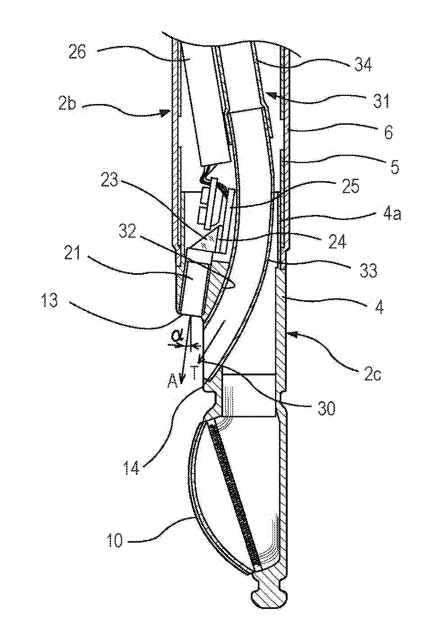
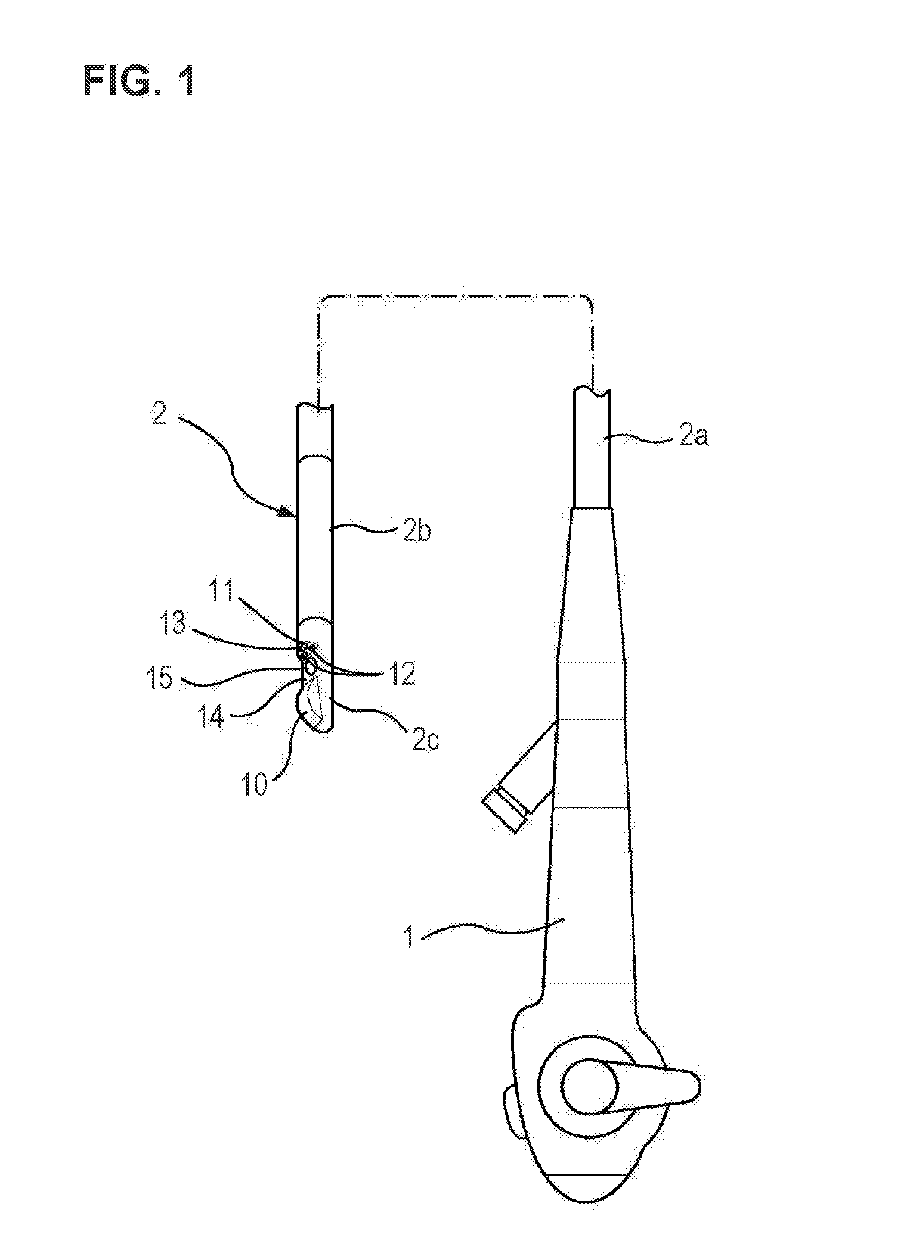
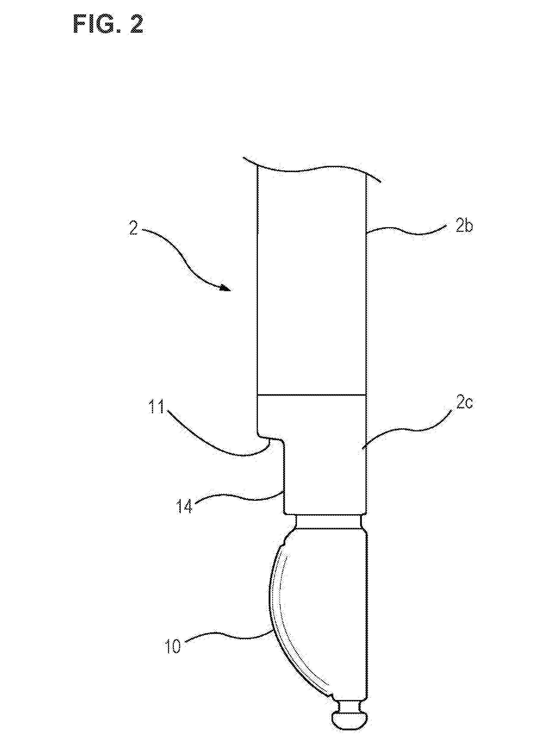
[0027]Hereinafter, embodiments of the present invention will be described with reference to the drawings. First, the overall configuration of an ultrasonic endoscope is shown in FIG. 1. In this drawing, reference numeral 1 designates a main body operating part, and reference numeral 2 designates an insertion part into a body cavity. The insertion part 2 includes a flexible portion 2a, a bending portion 2b, and a distal portion 2c which are continuously provided in this order at the main body operating part 1. In the insertion part 2, the longest portion is the flexible portion 2a, and the bending portion 2b is adapted so as to be capable of being bent and operated up and down or up and down and right and left. In addition, “up” indicates being directed to the ultrasonic observation mechanism side, and “down” indicates the opposite direction of “up”. Additionally, “left” indicates the left side toward the distal portion 2c, and “right” indicates the right side toward the distal porti...


PUM


Abstract

An observation unit can be stably held in a state where the observation unit is mounted on a distal portion, and can be easily removed without interfering with a connection pipe. A mounting hole for mounting an observation unit on a distal end body which constitutes a distal portion is formed. The mounting hole is formed with a first holding portion into which the distal portion of the lens barrel is inserted, a second holding portion into which a prism holder is inserted, and a releasing portion having a space larger than the external diameter of the lens barrel between the first and second holding portions.

Description

BACKGROUND OF THE INVENTION[0001]1. Field of the Invention[0002]The present invention relates to an endoscope in which the distal portion of the insertion part is provided with an endoscope observation mechanism.[0003]2. Description of the Related Art[0004]Endoscopes are configured such that the insertion part composed of a flexible portion, a bending portion, and a distal portion is provided so as to be connected to a main body operating part, and an endoscope observation mechanism is provided at the distal portion. Among these endoscopes, an endoscope is disclosed in JP2007-252458A. In this JP2007-252458A, an endoscope observation mechanism is of an oblique-front-viewing type in which the observation visual field is set to be obliquely forward.[0005]When ultrasonic scanning is performed within the body of a subject by using an ultrasonic transducer which constitutes an ultrasonic observation mechanism, if an affected part or a part suspected to be an affected part is detected, thi...

Claims


Application Information

Patent Timeline
IPC IPC(8): A61B1/018
CPCA61B1/00087A61B8/445A61B8/12A61B1/018
Inventor MORIMOTO, YASUHIKO
Owner FUJIFILM CORP
Why Eureka
Try Eureka