
Webbing take-up device

Inactive Publication Date: 2011-12-15
KK TOKAI RIKA DENKI SEISAKUSHO
View PDF6 Cites 3 Cited by
  • Summary
  • Abstract
  • Description
  • Claims
  • Application Information

AI Technical Summary

Benefits of technology

[0007]In consideration of the above-mentioned facts, the present invention has an object to provide a webbing take-up device capable of enhancing an axis positional accuracy of a torsion shaft with respect to a spool in a case where one side end in the axial direction of the torsion shaft is held by the intermediate portion in the axial direction in the spool.
[0014]Further, the engagement protrusions are provided on the held portion of the torsion shaft, the engagement protrusions are into an engaged (caught) state in which the engagement protrusions face the engagement surfaces and abut with lateral side surfaces of the engagement grooves by causing the torsion shaft to be rotated relatively to the spool about an axis of the torsion shaft under a state in which the held portion is inserted in the spool and passes over the insertion grooves.
[0016]As described hereinabove, the webbing take-up device according to the first aspect of the present invention provides an excellent effect capable of enhancing the axis positional accuracy of the torsion shaft with respect to the spool.
[0017]The webbing take-up device according to the second aspect of the present invention provides such an excellent effect that the engagement protrusions of the torsion shaft are engaged in the spool, and successively, the torsion shaft can be arranged coaxially with the sleeve.

Problems solved by technology

Thus, it is difficult to enhance the axis positional accuracy of the torsion shaft with respect to the spool on a side of the intermediate portion in the axial direction in the spool.

Method used


Image

  • Webbing take-up device
  • Webbing take-up device
  • Webbing take-up device

Examples


an embodiment

Structure of an Embodiment

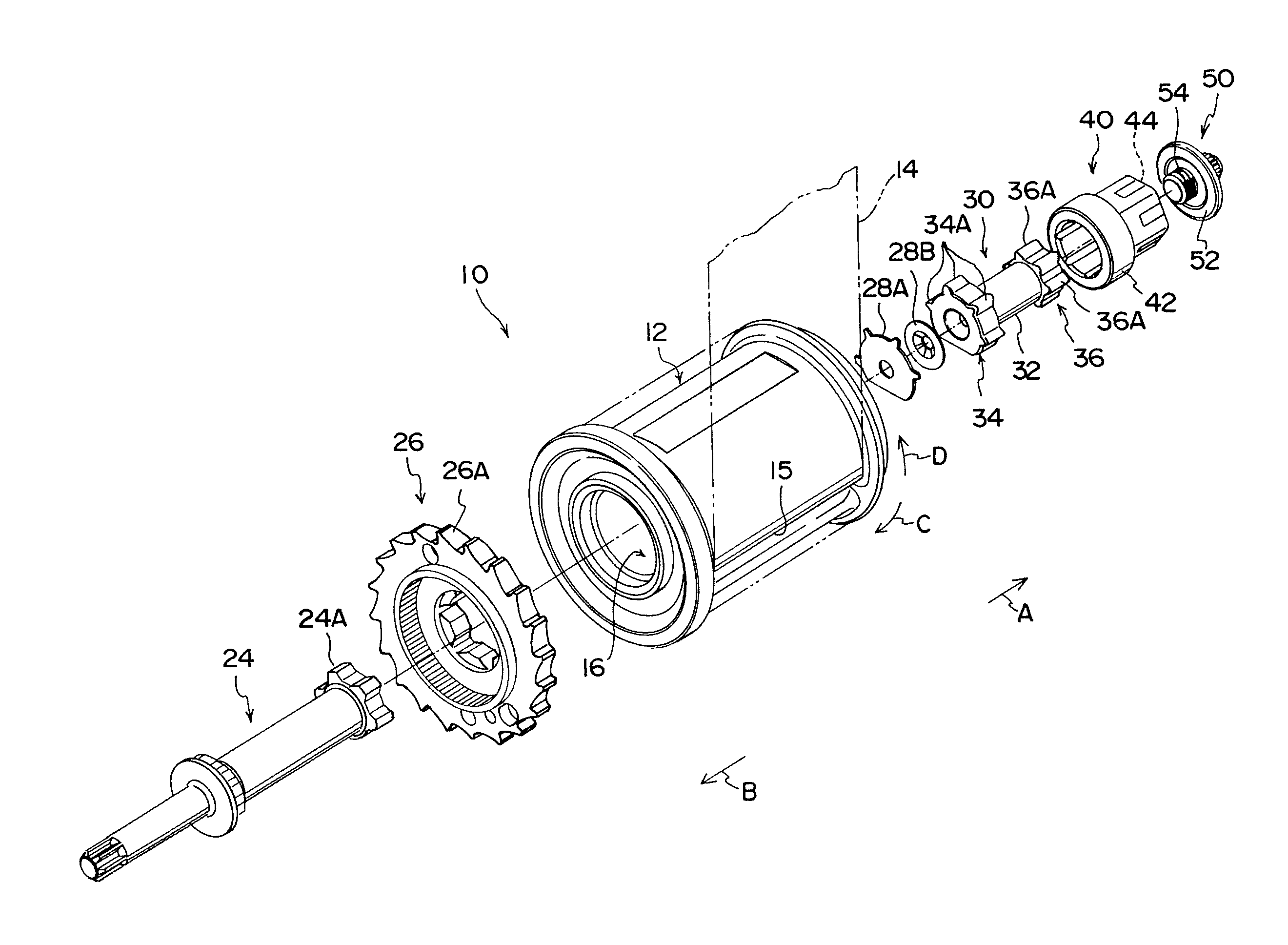
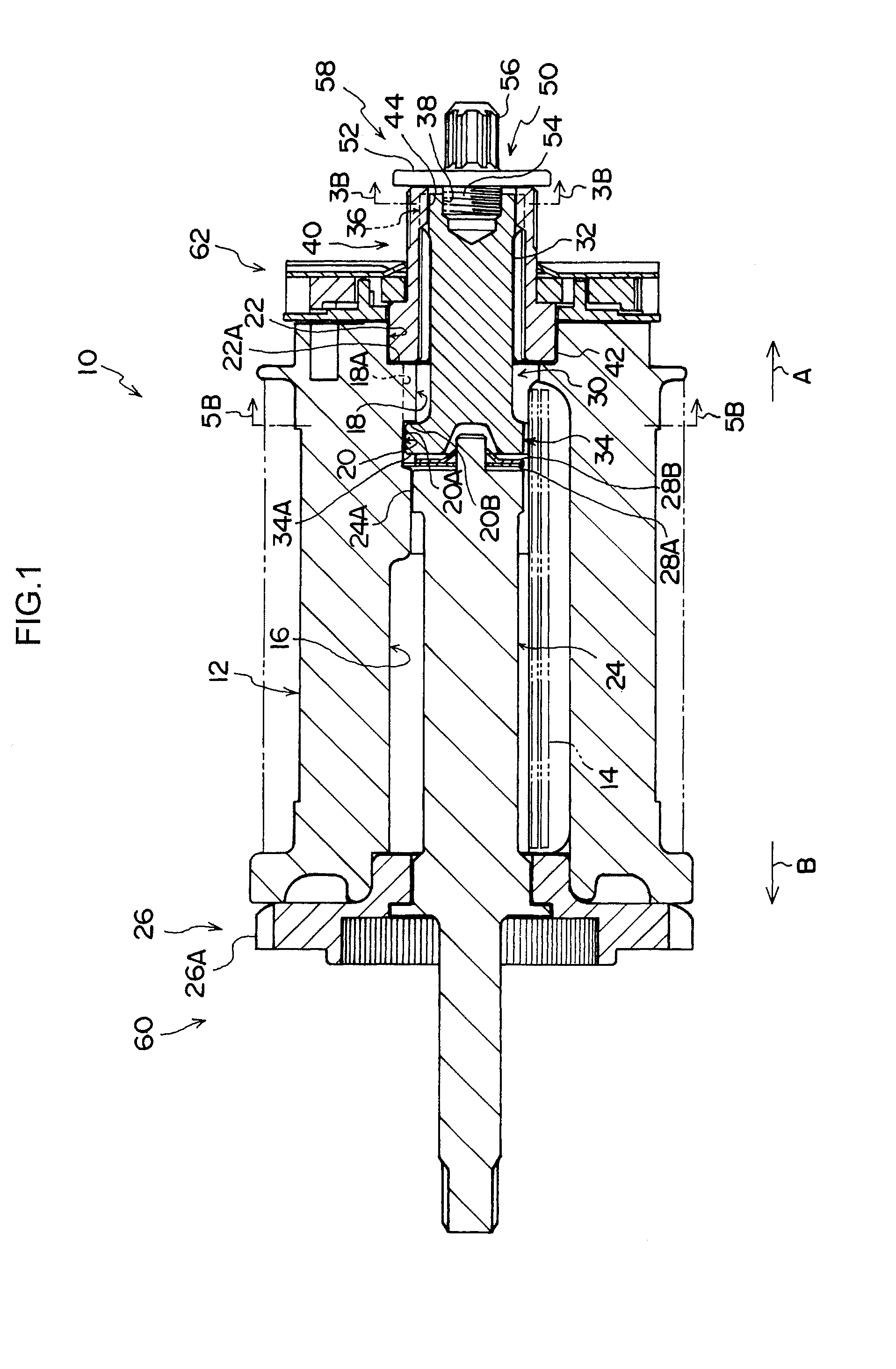
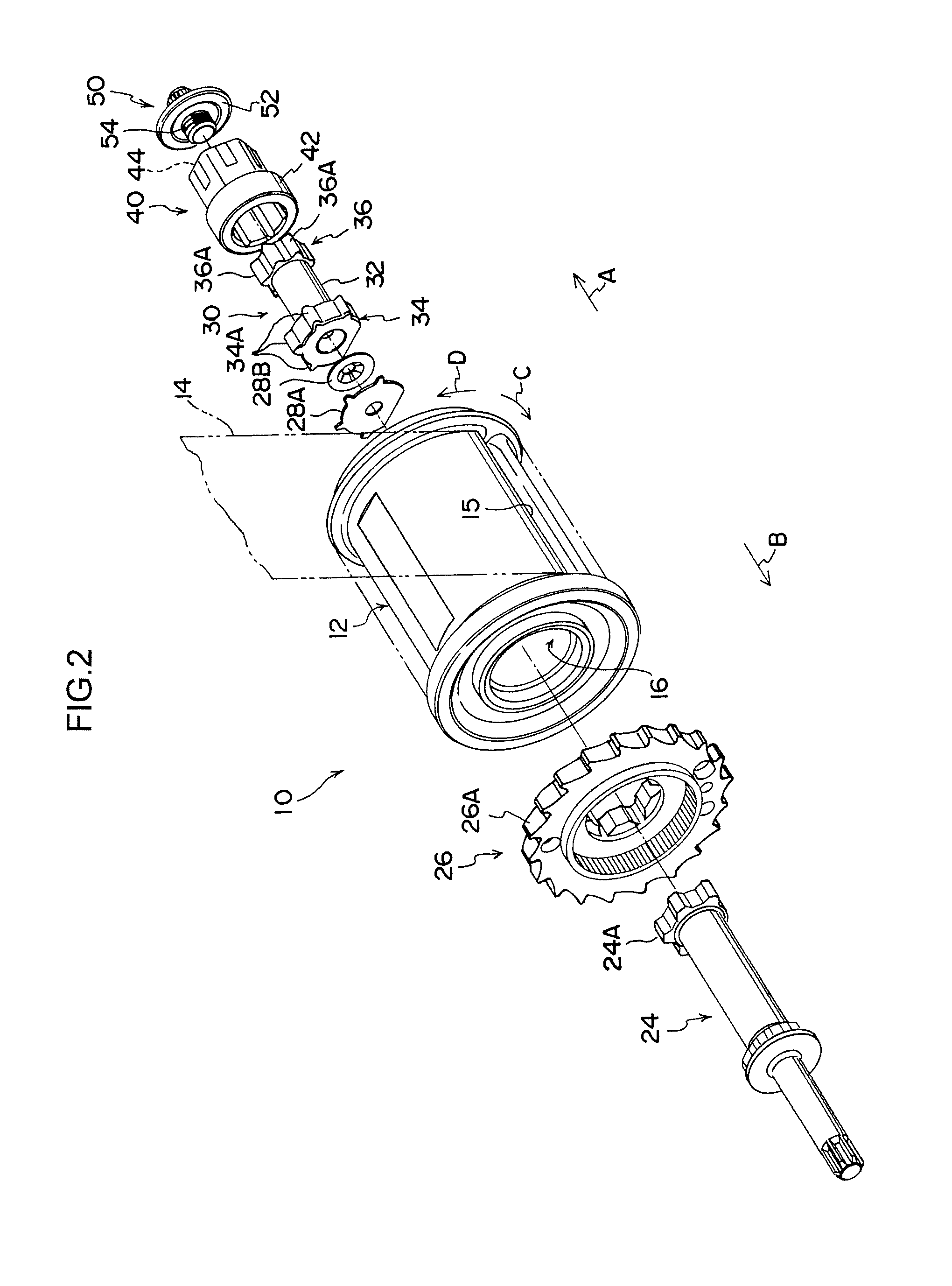
[0024]FIG. 1 is a cross-sectional view of a webbing take-up device 10 according to an embodiment of the present invention, and FIG. 2 is an exploded perspective view of a main part (shaft-assembled section) of the webbing take-up device 10. Note that, in the figures, one side in an axial direction of the spool 12 in the webbing take-up device 10 is indicated by an arrow A and another side in the axial direction of the spool 12 is indicated by an arrow B.

[0025]As illustrated in FIGS. 1 and 2, the webbing take-up device 10 according to this embodiment includes a spool 12 constituting a take-up shaft. The spool 12 is formed in a substantially cylindrical (tube) shape by die-casting, and the spool 12 includes both end portions in the axial direction which are rotatably supported by a frame (not shown in the drawings) fixed to a vehicle.

[0026]As illustrated in FIG. 2, the spool 12 is provided with a webbing-passing (webbing-inserted) hole 15 opening with an elon...


PUM


Abstract

A sleeve is fitted in a spool so as to be arranged coaxially with the spool. A fit-insertion hole including plural female splines is formed on a cylindrical inner side of the sleeve coaxially with an axial line of the sleeve. A fit-insertion portion, which is fit-inserted in the fit-insertion hole, of a sub torsion shaft is coaxial with an axial line of the sub torsion shaft and provided with plural male splines formed on an outer peripheral side of the fit-insertion portion. As a result of rotational displacement of the sleeve about the axial line thereof and regulation of rotation of the sub torsion shaft, so an axial center of the fit-insertion portion is made to coincide with an axial center of the fit-insertion hole, a fit-insertion portion side of the sub torsion shaft is fixed by a fixing mechanism with respect to the sleeve.

Description

CROSS-REFERENCE TO RELATED APPLICATION[0001]This application claims priority under 35 USC 119 from Japanese Patent Application No. 2010-135163 filed Jun. 14, 2010, the disclosure of which is incorporated by reference herein.BACKGROUND OF THE INVENTION[0002]1. Field of the Invention[0003]The present invention relates to a webbing take-up device in which a torsion shaft is assembled to a spool.[0004]2. Related Art[0005]There is known a webbing take-up device in which two energy-absorbing members which are a main shaft and a sub shaft as torsion shafts are arranged inside a spool (for example, refer to Japanese Patent Application Laid-Open (JP-A) No. 2009-113551). Those main shaft and sub shaft are arranged coaxially with the spool, and if axis positional accuracy thereof are enhanced, satisfactory drawing-out feeling of a webbing belt is obtained.[0006]However, at a time when the main shaft and the sub shaft are each held by an intermediate portion in the axial direction in the spool,...

Claims


Application Information

Patent Timeline
IPC IPC(8): B60R22/28B60R22/34
CPCB60R2022/287B60R22/3413
Inventor MAEKUBO, YOSHIAKIUKITA, MASARUYANAGAWA, WATARU
Owner KK TOKAI RIKA DENKI SEISAKUSHO
Learn More