A Rotary Cutting Tool with Accurate Axial Positioning

A rotary cutting tool, axial positioning technology, applied in milling cutters, manufacturing tools, metal processing equipment, etc., can solve the loosening or displacement of the tool holder 2 and the cutting insert, reduce the machining accuracy of the cutting tool, and the deformation of the tool holder fastener 4. and other problems to achieve the effect of avoiding deformation or collapse, improving safety and reducing load

Active Publication Date: 2016-12-28
ZHUZHOU CEMENTED CARBIDE CUTTING TOOLS CO LTD
View PDF5 Cites 0 Cited by
  • Summary
  • Abstract
  • Description
  • Claims
  • Application Information

AI Technical Summary

Problems solved by technology

However, when the end of the cutting blade 3 is subjected to the cutting force F1, the intersection line between the tool holder 2 and the end of the rotary cutter body 1 is the central axis O of the force, and the supporting force of the entire tool groove 11 on the tool holder 2 is concentrated. On the stressed central axis O, this structure makes the rotating cutter body 1 prone to deformation or collapse at the stressed central axis O; the torque generated by the cutting force F1 relative to the stressed central axis O can only be generated by the tool holder fastener The torque generated by the fastening force F2 of 4 is balanced, and the stability of the connection between the rotating tool body 1 and the tool holder 2 is completely guaranteed by the tool holder fastener 4. The greater the cutting force F1, the faster the tightening force generated by the tool holder fastener 4. The larger F2 is, the greater the force O of the rotating cutter body 1 is likely to be deformed or broken, which will cause loosening or displacement of the tool holder 2 and cutting blade 3, thereby greatly reducing the machining accuracy of the cutting tool. The fastener 4 may also be deformed or even broken due to excessive force, and the broken tool holder fastener 4 will fly out, which greatly challenges the safety

Method used


Image

  • A Rotary Cutting Tool with Accurate Axial Positioning
  • A Rotary Cutting Tool with Accurate Axial Positioning
  • A Rotary Cutting Tool with Accurate Axial Positioning

Examples


Embodiment Construction

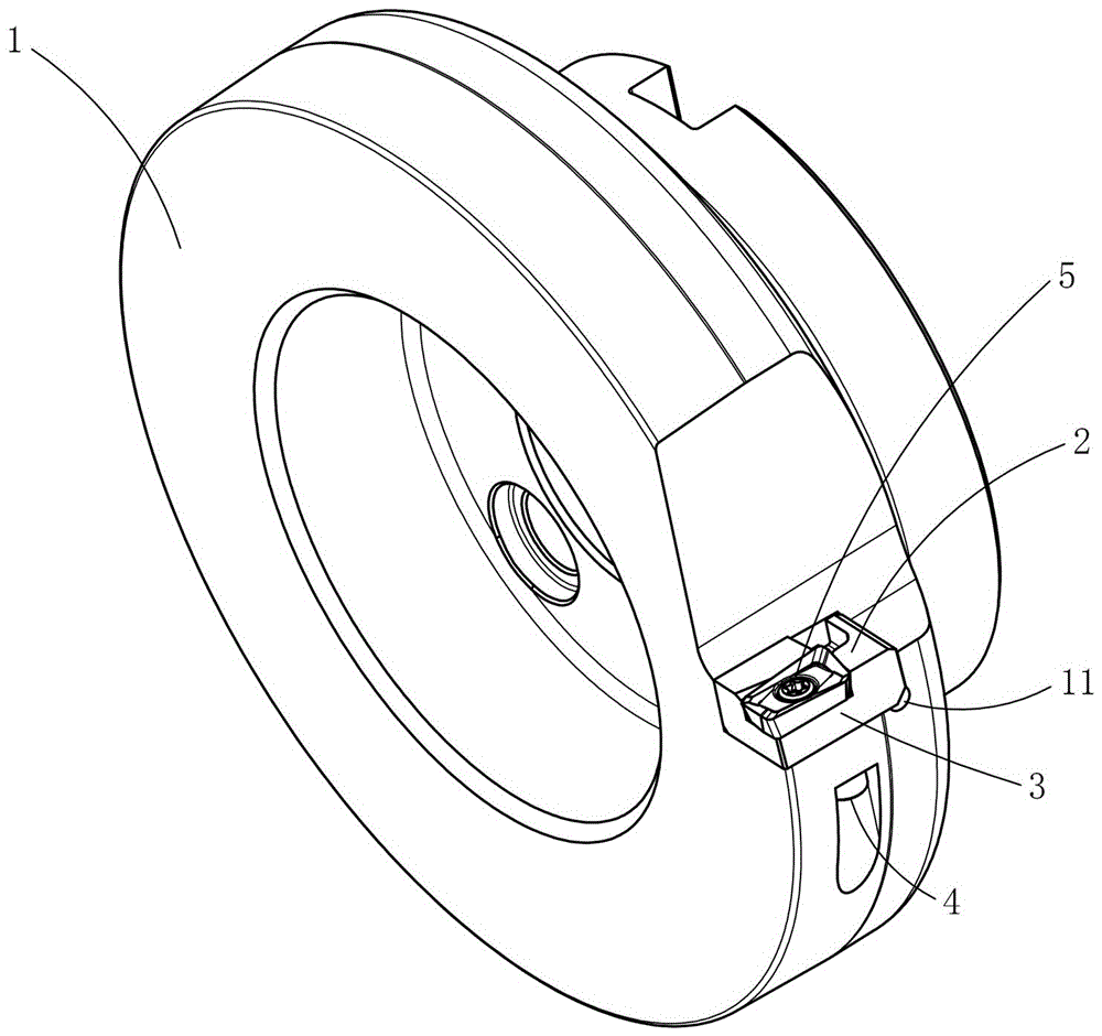
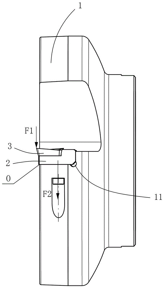
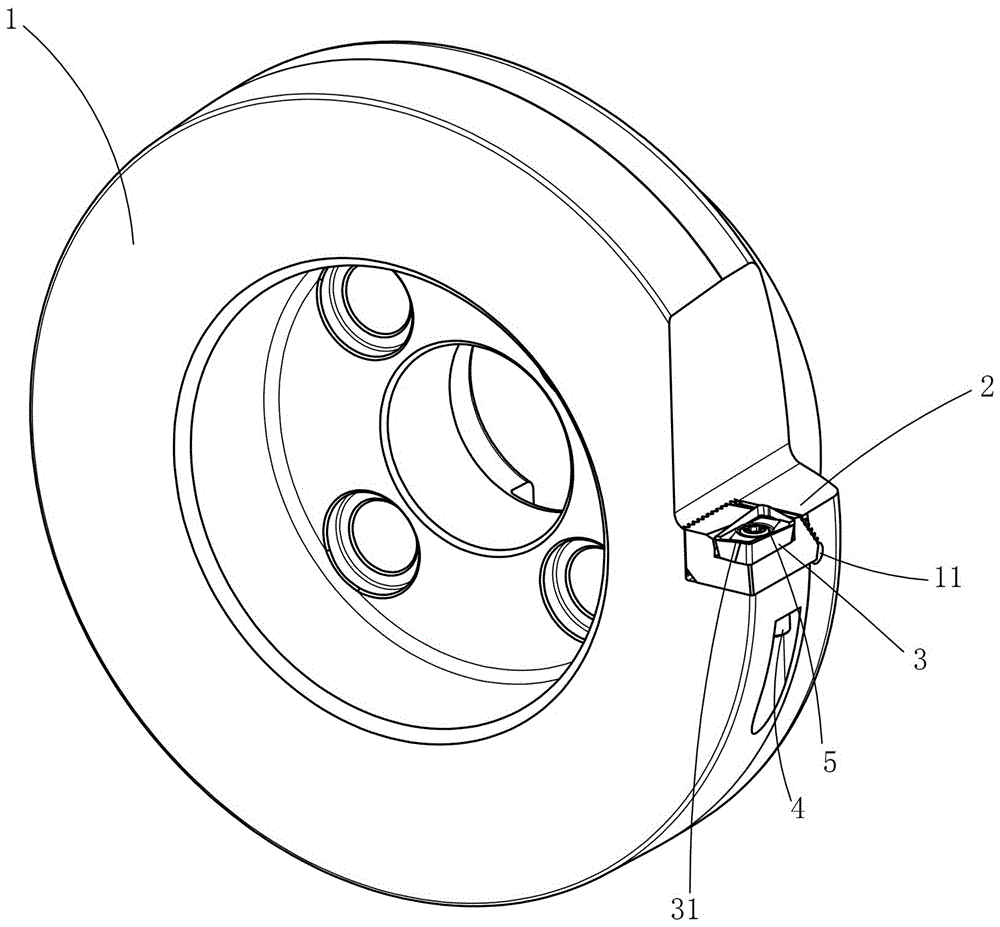
[0039] Figure 3 to Figure 6It shows the first embodiment of the rotary cutting tool with accurate axial positioning of the present invention, including a rotary cutter body 1, a tool holder 2, a cutting blade 3, a tool holder fastener 4 and a blade fastener 5, and the rotary cutter body 1 The top is provided with the sipe 11 surrounded by the bottom positioning surface 111, the first side positioning surface 112 and the second side positioning surface 113. The cutting blade 3 is fixed on the tool holder 2 by the blade fastener 5. The first side positioning surface 112 is the opposite surface of the knife groove 11 and the end cutting edge 31 of the cutting blade 3, the tool holder 2 is inserted into the knife groove 11 along the radial direction of the rotating cutter body 1, and the first side positioning surface 112 and the bottom positioning surface 111 are formed on the tool holder 2 Interference clamping and positioning, the tool holder fastener 4 is connected and fixed ...


PUM


Abstract

The invention discloses a rotary cutting tool capable of axially and accurately locating. The rotary cutting tool comprises a rotary cutter body, a cutter holder, a cutting blade, a cutter holder fastening part and a cutting blade fastening part, wherein a cutter slot defined by a bottom locating surface, a first side locating surface and a second side locating surface is formed in the rotary cutter body, the cutting blade is fixed on the cutter holder by the cutting blade fastening part, the first side locating surface is a surface at which the cutter slot is opposite to an end cutting edge of the cutting blade, the cutter holder is radically inserted in the cutter slot along the rotary cutter body, the first side locating surface and the bottom locating surface form interference clamping locating to the cutter holder, and the cutter holder and the rotary cutter body are fixedly connected with each other by the cutter holder fastening part. The rotary cutting tool capable of axially and accurately locating has the advantages of high axial anti-shock capability, high locating precision, good safety and long service life.

Description

technical field [0001] The invention relates to a metal cutting tool, in particular to a rotary cutting tool with accurate axial positioning. Background technique [0002] Currently, people generally use figure 1 with figure 2 The rotary cutting tool shown includes a rotary cutter body 1, a tool holder 2, a cutting blade 3, a tool holder fastener 4 and a blade fastener 5, and the rotary cutter body 1 is provided with at least one set of tool grooves 11 , the cutting blade 3 is fixed on the tool holder 2 by the blade fastener 5 and placed in the tool groove 11 together with the tool holder 2. In this structure, the tool holder 2 is directly fixed by the tool holder fastener 4, and the tool holder 2 can be stably fixed in the knife groove 11. However, when the end of the cutting blade 3 is subjected to the cutting force F1, the intersection line between the tool holder 2 and the end of the rotary cutter body 1 is the central axis O of the force, and the supporting force of...

Claims


Application Information

Patent Timeline
Patent Type & Authority Patents(China)
IPC IPC(8): B23C5/22
Inventor 江爱胜王社权汤爱民刘敏陈林易为
Owner ZHUZHOU CEMENTED CARBIDE CUTTING TOOLS CO LTD
Why Eureka
Try Eureka