Clamping and positioning method and tool for special-shaped transverse beam

A technology for positioning tooling and positioning method, applied in positioning devices, clamping, manufacturing tools, etc., can solve the problems of reducing the machining efficiency and quality of beams, poor clamping stability, and difficult operation, and shortening the clamping and positioning time. , The effect of improving rigidity and expanding the scope of application

Active Publication Date: 2019-04-16
江阴市惠尔信精密装备股份有限公司
View PDF11 Cites 0 Cited by
  • Summary
  • Abstract
  • Description
  • Claims
  • Application Information

AI Technical Summary

Problems solved by technology

[0003] However, the above-mentioned clamping and fixing method for beams is mainly applicable to beams of conventional structures. Figure 5 The large-scale beam in a certain textile machinery shown in the figure has a special-shaped cross-sectional shape (the front side of the beam is flat, and a special-shaped surface is formed between the upper end surface of the beam, the lower end surface of the beam and the rear side of the beam), according to the process requirements , the beam needs to be placed horizontally during processing, and the front side of the beam is required to be positioned vertically before clamping and fixing. If the conventional method is used for clamping, the operation is difficult, and the clamping efficiency is low and the clamping stability is also low. Poor, resulting in the inability to withstand the increased cutting force during subsequent machining, thereby reducing the efficiency and quality of machining the beam

Method used


Image

  • Clamping and positioning method and tool for special-shaped transverse beam
  • Clamping and positioning method and tool for special-shaped transverse beam
  • Clamping and positioning method and tool for special-shaped transverse beam

Examples


Embodiment 1

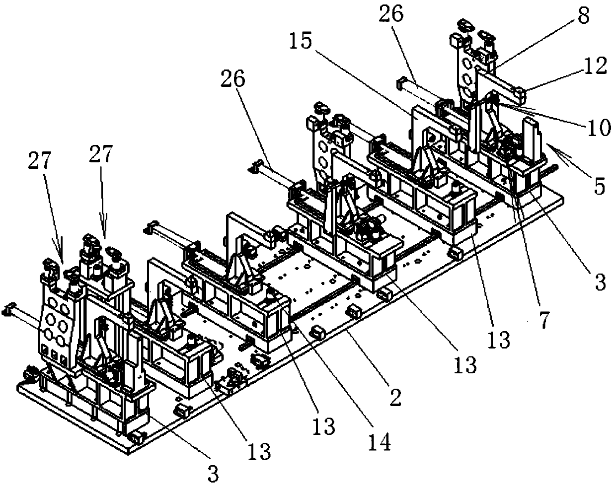
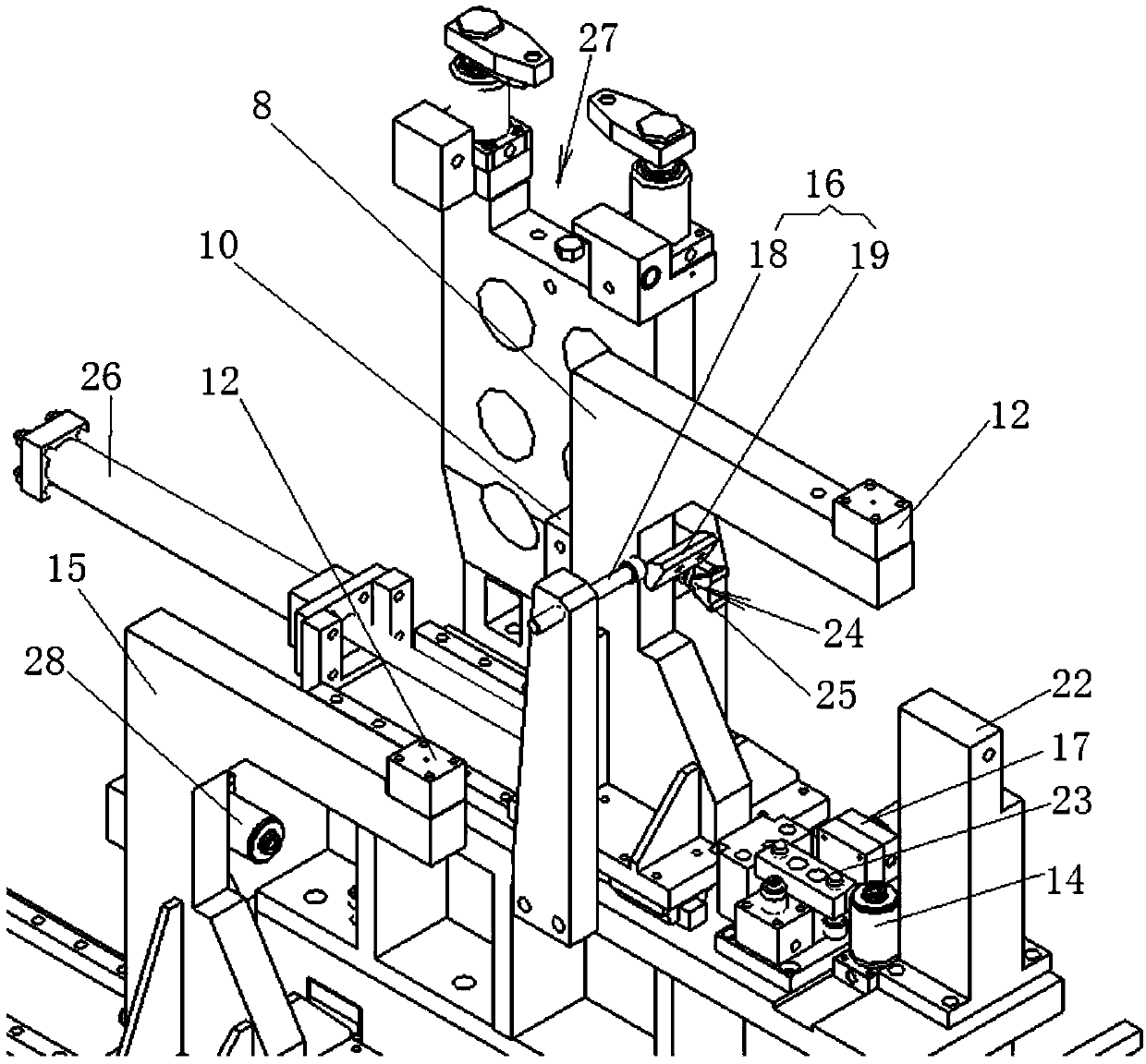
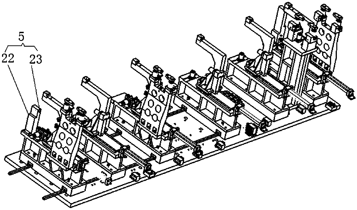
[0053] Such as Figures 1 to 5 Shown is an embodiment of a clamping and positioning method for a special-shaped beam, including the following method steps:

[0054] (1) Setting of the clamping and positioning tooling: a main base 3 is respectively arranged at the left and right ends of the base plate 2, and several sub-bases 13 are arranged between the main bases 3, and on the main base 3 and the sub-bases 13 The main moving frame 8 and the auxiliary moving frame 15 are respectively arranged, and the front side positioning element 5 and the bottom end surface positioning element 7 for positioning the beam are arranged on the main base 3, and the lateral tightening element 10 is set on the main moving frame 8 And the vertical pressing element 12, the floating support oil cylinder 14 that is used to auxiliary support the bottom end face 6 of the beam is set on the auxiliary base 13 at the same time, and the auxiliary side top element 28 and the vertical pressing element 12 are s...

Embodiment 2

[0065] Such as Figures 1 to 5 Shown is an embodiment of a clamping and positioning tool for a special-shaped beam of the present invention, including a base plate 2, a main base 3 respectively arranged on the upper plane of the left end of the base plate 2 and the upper plane of the right end of the base plate 2, and the main base 3 The front upper plane of the front part of the main base 3 is respectively provided with a front side positioning element 5 for positioning the front side of the beam 4 and a bottom surface positioning element 7 for positioning the bottom end surface 6 of the beam. The rear part of the main base 3 is provided with a The moving main mobile frame 8 is respectively provided with a lateral pressing element 10 for pressing the rear side 9 of the crossbeam and a vertical pressing element 12 for pressing the upper end surface 11 of the crossbeam on the main moving frame 8. The main mobile frame 8 moves backward to the position before the hoisting and pos...


PUM


Abstract

The invention relates to the technical field of machining process equipment, and discloses a clamping and positioning method and tool for a special-shaped transverse beam. The clamping and positioningmethod comprises the steps of arranging of the clamping and positioning tool, arranging of a hydraulic system, adjusting of the clamping and positioning tool, arranging of a hoisting space of a transverse beam, hoisting and positioning of the transverse beam, and clamping of the transverse beam. The clamping and positioning tool comprises a bottom plate and main bases arranged on the left end upper plane and the right end upper plane of the bottom plate correspondingly, and the front upper plane of each main base is provided with a front side face positioning element used for positioning thefront side face of the transverse beam, and a bottom end face positioning element used for positioning the bottom end face of the transverse beam; a main moving frame capable of moving in the front-rear direction is arranged on the rear part of each main base; and each main moving frame is provided with a lateral jacking element used for jacking the rear side face of the transverse beam, and a vertical compressing element used for compressing the upper end face of the transverse beam. According to the clamping and positioning method and tool for the special-shaped transverse beam, the convenience and stability of clamping and positioning operation of the transverse beam are improved.

Description

technical field [0001] The invention relates to the technical field of machining process equipment, in particular to a clamping and positioning method for a special-shaped beam and a clamping and positioning tool. Background technique [0002] The beam is a mechanical part widely used in mechanical equipment. It is mainly used as an installation carrier for other parts in the mechanical equipment. It needs to bear a large load and requires high precision. When the beam is machined, the beam needs to be clamped and fixed. The conventional clamping and fixing method is to use a pad and a pressure plate to lean the lower part of the beam against the pad, and press and fix the top with a pressure plate. For beams with high precision requirements, CNC machine tools or machining centers are usually used for machining beams. [0003] However, the above-mentioned clamping and fixing method for beams is mainly applicable to beams of conventional structures. Figure 5 The large-scale...

Claims


Application Information

Patent Timeline
Patent Type & Authority Applications(China)
IPC IPC(8): B23Q3/08
CPCB23Q3/08B23Q3/082
Inventor 徐惠民罗旭王杰
Owner 江阴市惠尔信精密装备股份有限公司
Why Eureka
Try Eureka