Gear ring turning clamp with axial positioning structure

A technology of axial positioning and car fixtures, which is applied to components with teeth, gear teeth, gear cutting machines, etc., and can solve problems such as meshing quality degradation

Pending Publication Date: 2021-05-18
JIANGSU PACIFIC GEAR DRIVE CO LTD +1
View PDF0 Cites 0 Cited by
  • Summary
  • Abstract
  • Description
  • Claims
  • Application Information

AI Technical Summary

Problems solved by technology

If the tip of the tooth is miscut, the mes...

Method used


Image

  • Gear ring turning clamp with axial positioning structure
  • Gear ring turning clamp with axial positioning structure
  • Gear ring turning clamp with axial positioning structure

Examples


Embodiment Construction

[0019] The present invention will be further described below according to the accompanying drawings and in conjunction with the embodiments.

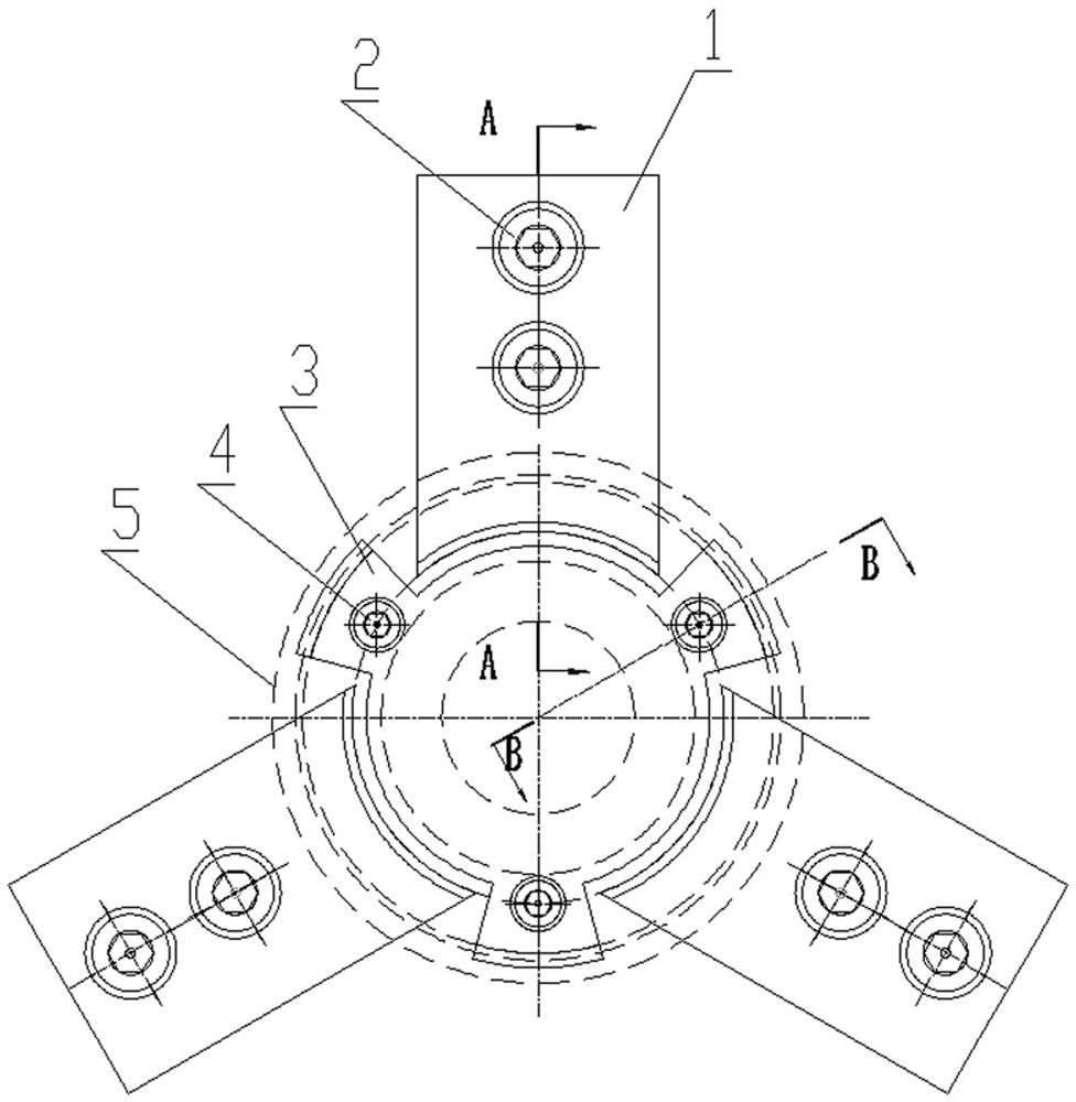
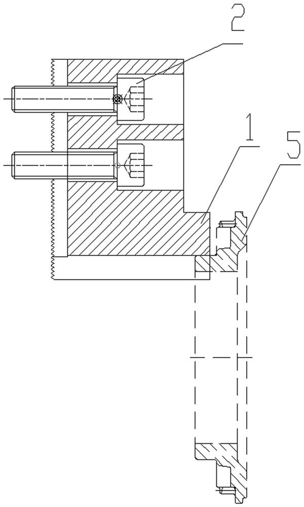
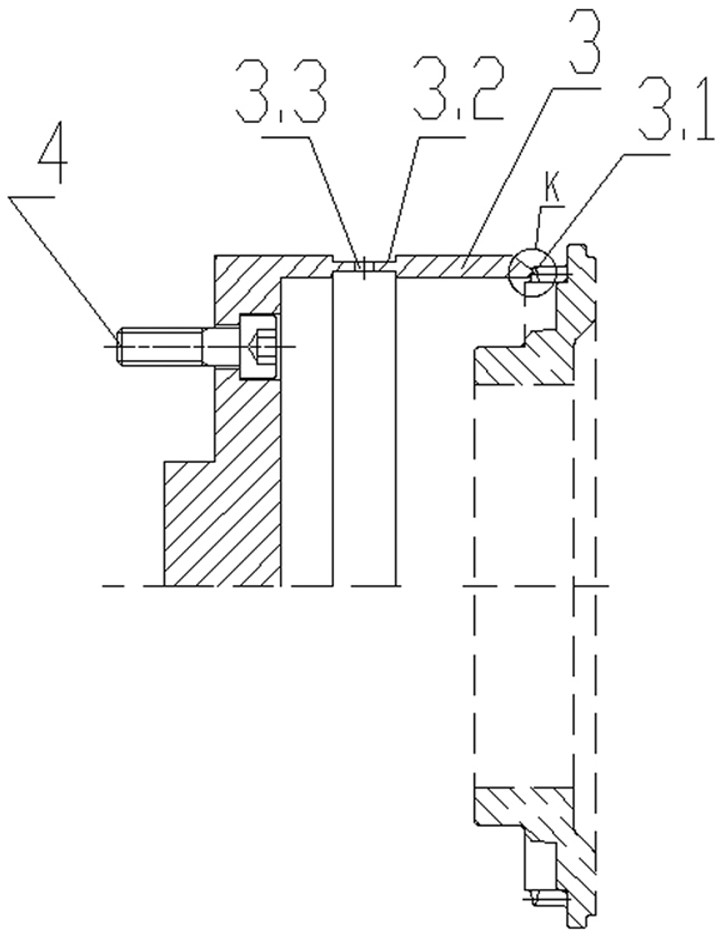
[0020] figure 1 Shown is a ring gear jig with an axial positioning structure, which includes a pressure block 1, a bolt 2, a three-leaf disc 3 and a bolt 4. The briquetting block 1 is used to clamp the workpiece ring gear 5, which is a rectangular block member made of soft metal. The workpiece ring gear 5 turned in this embodiment is matched with a car gearbox, and the briquetting block 1 made is selected from Made of silicon brass. In the vehicle fixture structure, the pressure block 1 is directly attached to the jaws of the matching three-jaw chuck and locked with a bolt 2 to form a self-centering clamping structure in which the pressure block 1 moves radially with the three-jaw chuck. figure 2 The pressing block 1 shown in the figure directly presses the inner and outer shoulders of the ring gear 5, and this kind of three-equal pr...


PUM


Abstract

The invention discloses a gear ring turning clamp with an axial positioning structure. The gear ring turning clamp comprises a pressing block, a first bolt, a three-blade plate and a second bolt, wherein the pressing block is directly attached to a matching three-jaw chuck jaw and locked through the first bolt, a self-centering clamping structure that the pressing block moves in the radial direction along with the three-jaw chuck jaw is formed, the three-blade plate is positioned and installed in the middle of the end face, provided with clamping jaws, of the three-jaw chuck, the three-blade plate and the three-jaw chuck are connected in a locked mode through the second bolt, the three-blade plate is provided with three fan-shaped blades which extend out in the radial direction and are staggered with the clamping jaws of the three-jaw chuck, the radial outer edge of each fan-shaped blade is bent inwards in an angular mode according to the combination of the size of the gear tooth tips uniformly arranged in the gear ring, and an axial positioning structure in combination with the built-in gear tooth tip of the gear ring for limiting is formed. The radial clamping structure and the axial positioning structure adopt a discrete mode, so that a positioning component does not bear clamping force structurally, and the gear ring is axially positioned after being installed in place.

Description

technical field [0001] The invention belongs to a technical solution in the technical field of machining fixtures. Specifically, the invention relates to a turning fixture, especially a ring gear turning fixture provided with an axial positioning structure. Background technique [0002] The ring gear is a double gear consisting of an external gear and a combined gear. It is an essential transmission component in an automobile gearbox. The gearbox for automobiles is very compact in structure and relatively small in size, and the supporting ring gear is limited in structure and size, so the axial dimension is small. When this kind of annular ring gear is mass-produced, the industry prefers the precision forging forming process to make the billet, and then only the inner hole and the end surface are processed by micro-finishing. Because the two gears built into the ring gear have been precisely forged, coupled with structural limitations, only the outer shoulder can be clamped...

Claims


Application Information

Patent Timeline
IPC IPC(8): B23F23/06
CPCB23F23/06
Inventor 徐树存夏宇焦继松吴江
Owner JIANGSU PACIFIC GEAR DRIVE CO LTD
Why Eureka
Try Eureka