LED tube lamp

a technology of led tube lamps and led tubes, which is applied in the direction of point-like light sources, semiconductor devices for light sources, lighting and heating apparatus, etc., can solve the problem that the light divergence angle of led tube lamps cannot be increased

Inactive Publication Date: 2011-12-15
HON HAI PRECISION IND CO LTD
View PDF2 Cites 83 Cited by
  • Summary
  • Abstract
  • Description
  • Claims
  • Application Information

AI Technical Summary

Problems solved by technology

All the LEDs in the LED array emit light in the same direction, with this kind of LED array, the light divergence angle of LED tube lamps cannot be increased.

Method used


Image

  • LED tube lamp
  • LED tube lamp
  • LED tube lamp

Examples


Embodiment Construction

[0013]Embodiments of the present disclosure are now described in detail, with reference to the accompanying drawings.

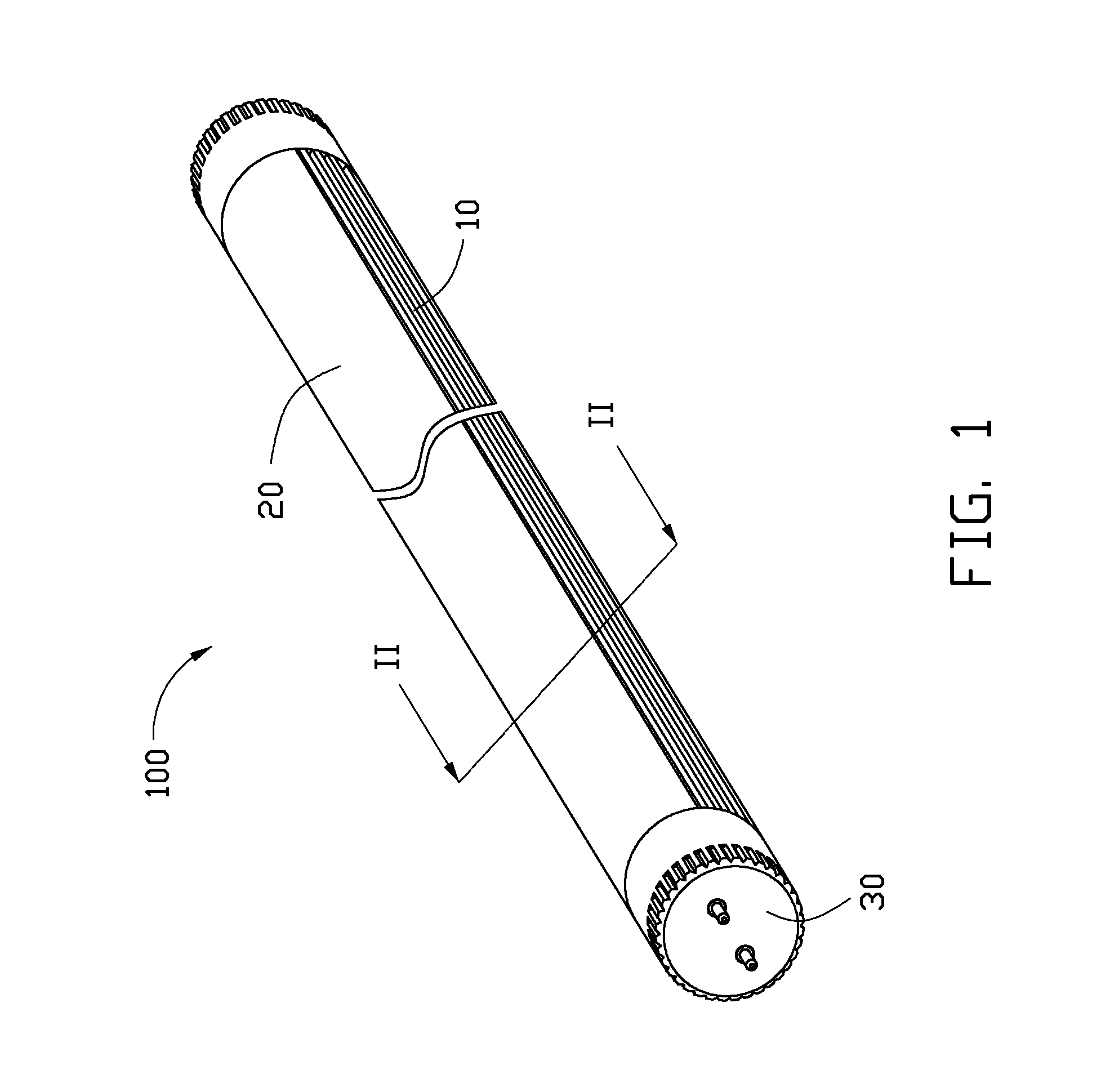
[0014]Referring to FIG. 1, an embodiment of an LED tube lamp 100 is illustrated.

[0015]The LED tube lamp 100 includes a heat sink 10, a cover 20, and a pair of connectors 30. The cover 20 is fixed to the heat sink 10, has an elongated structure, and has an arc-shaped cross section. The connectors 30 are arranged at opposite ends of the LED tube lamp 100 and are used to connect to a coupling connector (not shown), thus electrically connecting the LED tube lamp 100 to a power source.

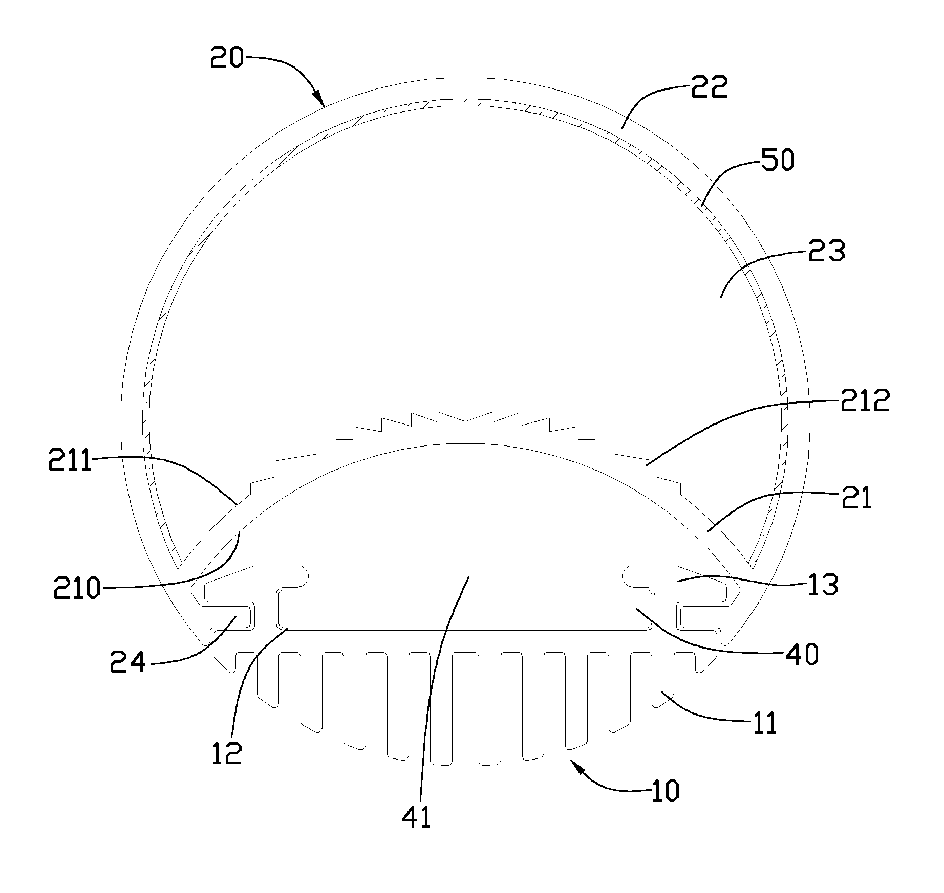
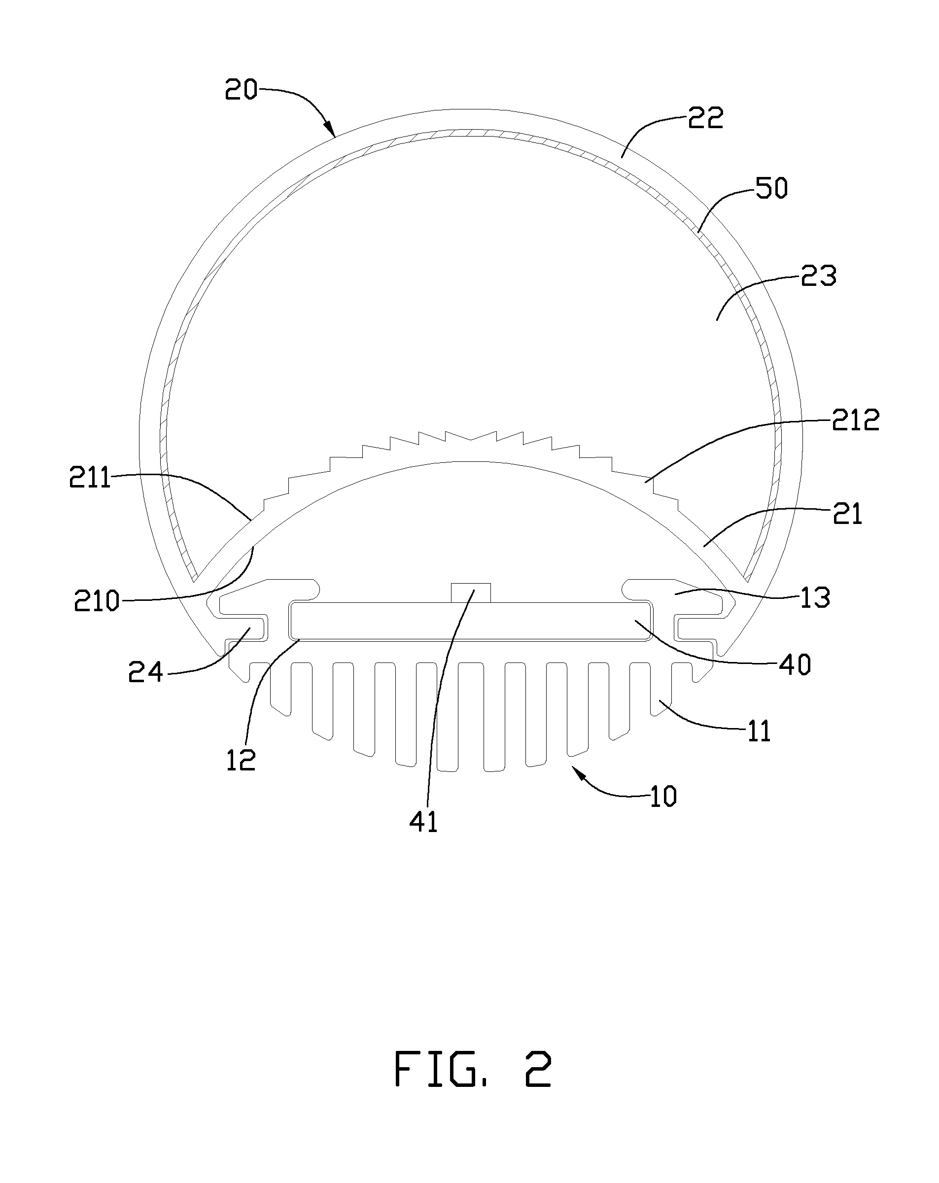
[0016]Referring to FIG. 2, the LED tube lamp 100 further includes an LED substrate 40 mounted on the heat sink 10 and electrically connected to the connector 30. A plurality of LEDs 41 are arranged on the LED substrate 40. The LEDs 41 can be chosen for having a large light divergence angle, high illumination, and / or being colored according to actual requirements.

[0017]The heat sink 10 has an ...


PUM

PropertyMeasurementUnit
transparentaaaaaaaaaa
luminous efficiencyaaaaaaaaaa
light divergence angleaaaaaaaaaa

Abstract

An LED tube lamp includes a heat sink, an LED substrate, a cover fixed to the heat sink. The cover includes a first cover and a second cover, the first cover is closer to the LED substrate than the second cover, and a plurality of lenses are arranged on the surface of the first cover to refract the light beams entering into the first cover. The light beams are scattered by the lenses to enlarge the light divergence angle of the LED tube lamp.

Description

BACKGROUND[0001]1. Technical Field[0002]The present disclosure relates to light emitting diode (LED) illuminating devices and, particularly, to an LED tube lamp.[0003]2. Description of Related Art[0004]Compared to traditional light sources, light emitting diodes (LEDs) have advantages, such as high luminous efficiency, low power consumption, and long service life. LED lights are widely used in many applications to replace typical fluorescent lamps and neon tube lamps.[0005]Typical LED tube lamps usually include a cylindrical tube and an LED substrate. However, in order to increase the illumination, a type of LED array including a plurality of LEDs connected in series arranged on the LED substrate is used in LED tube lamps. All the LEDs in the LED array emit light in the same direction, with this kind of LED array, the light divergence angle of LED tube lamps cannot be increased.[0006]Therefore, there is room for improvement in the art.BRIEF DESCRIPTION OF THE DRAWINGS[0007]Many aspe...

Claims


Application Information

Patent Timeline
Patent Type & Authority Applications(United States)
IPC IPC(8): F21V29/00
CPCF21K9/17F21V5/02F21Y2101/02F21V3/0472F21V29/89F21Y2103/003F21V29/75F21V29/763F21V29/86F21V3/049F21K9/27F21Y2103/10F21Y2115/10F21K9/69F21V3/10
Inventor CHANG, SHAO-HAN
Owner HON HAI PRECISION IND CO LTD
Why Eureka
Try Eureka