
Cutting Tool for Drilling and Turning

a cutting tool and cutting technology, applied in the field of cutting tools, can solve the problems of reducing cutting efficiency, affecting cutting accuracy, and affecting cutting accuracy, so as to facilitate chip discharge, enhance tool holder rigidity, and reduce vibration during cutting operations

Inactive Publication Date: 2011-12-15
TAEGUTEC
View PDF8 Cites 28 Cited by
  • Summary
  • Abstract
  • Description
  • Claims
  • Application Information

AI Technical Summary

Benefits of technology

[0013]According to the present invention, the cutting insert is securely supported in the tool holder. The rigidity of the tool holder is enhanced so that vibrations during cutting operations are reduced. In addition, chip discharge is facilitated, cutting resistance is diminished and lifetime of the tool holder is extended by the edge shape of the cutting insert and chip guide surface of the cutting tool of the present invention.

Problems solved by technology

Thus, a reinforcement portion (61) cannot be adequately secured.
This generates serious vibrations during machining, which in turn significantly reduces the cutting efficiency.
Thus, the breakage of the chips can be likely delayed and long chips may be produced.
The long chips can interfere with the feed of cutting oil, damage the workpiece and the insert tip, and cause poor chip discharge performance due to tangled chips.
This causes problems since it increases the cutting resistance and generates vibrations.
Further, this cutting tool has a problem since a portion of the front end of the tool holder, at which the cutting insert is not mounted, is damaged by the cutting chips generated during the cutting operation.
This reduces the life of the tool holder.

Method used


Image

  • Cutting Tool for Drilling and Turning
  • Cutting Tool for Drilling and Turning
  • Cutting Tool for Drilling and Turning

Examples


Embodiment Construction

[0021]The preferred embodiment of the present invention will be specifically described with reference to the drawings.

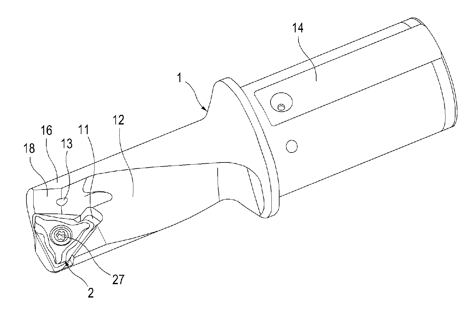
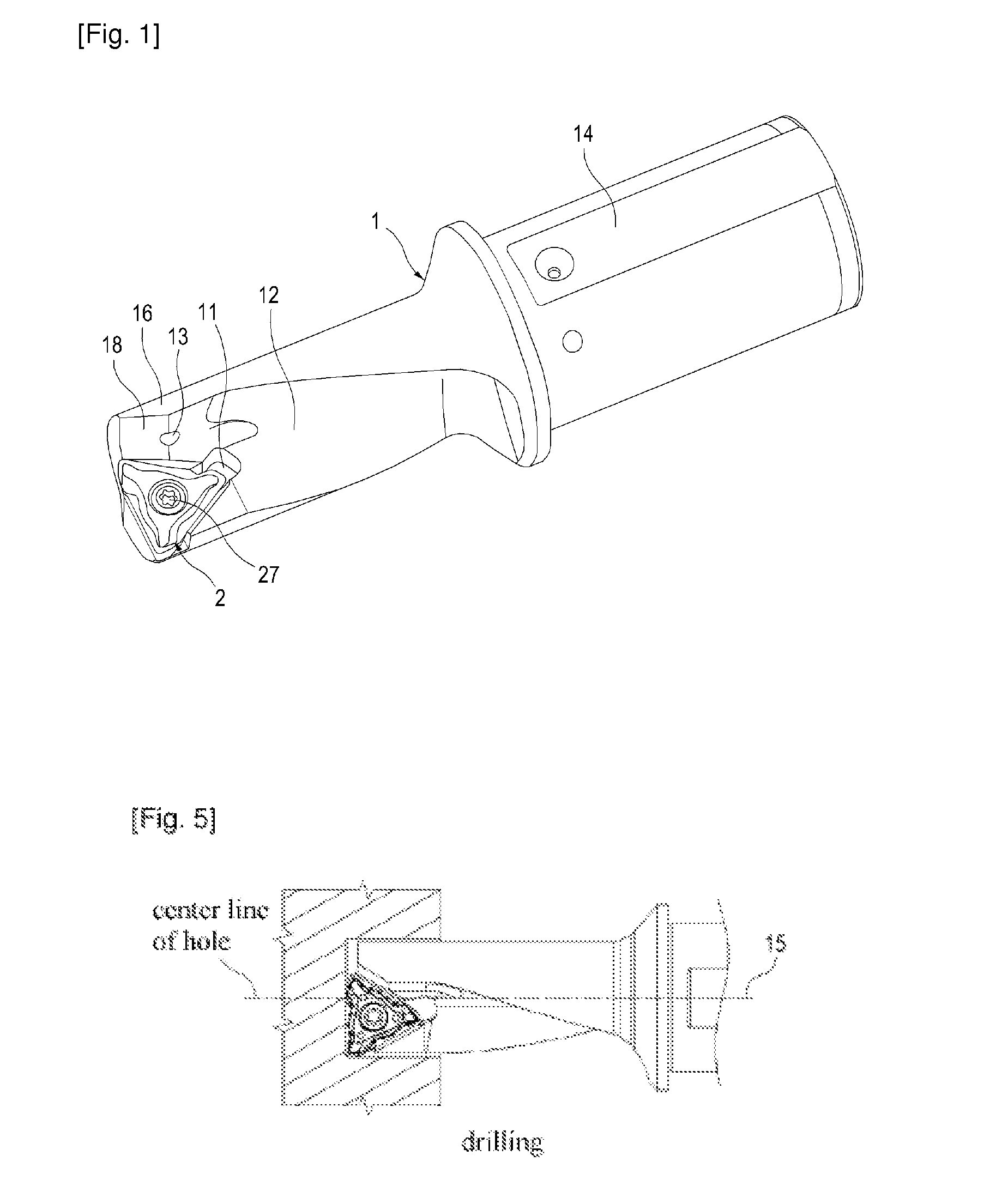
[0022]FIG. 1 shows a perspective view of a cutting tool according to the present invention, which is capable of drilling and turning. The cutting tool comprises a tool holder (1) and a cutting insert (2). The tool holder (1) is generally cylindrical and comprises a pocket (11) that receives the cutting insert (2), a chip discharge groove (12) that facilitates the discharge of chips, a cutting oil supply pipe (13) and a shank (14). A chip guide surface (18) is formed at the front end portion of the chip discharge groove (12) and extends to the peripheral surface of the tool holder (1). The chip guide surface (18) guides cutting chips generated from the cutting insert (2) at the front end portion of the chip discharge groove backwardly. The reinforce portion (16) formed behind the chip guide surface (18) enhances the rigidity of the tool holder (1).

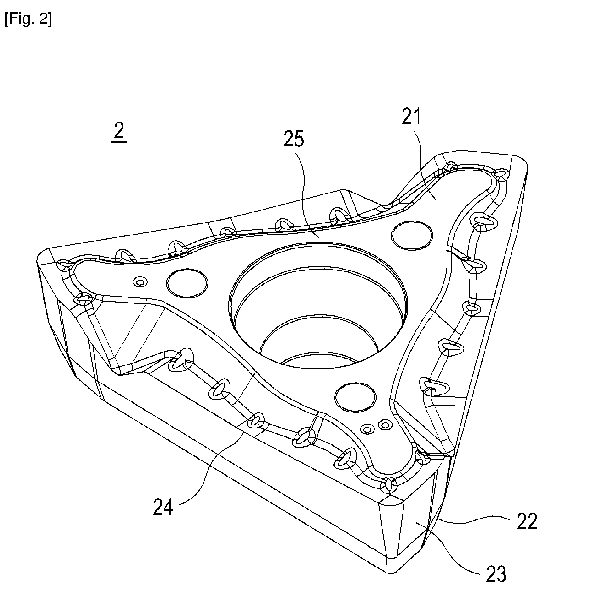
[0023]FIG. 2 shows a...


PUM

PropertyMeasurementUnit
Angleaaaaaaaaaa
Angleaaaaaaaaaa
Angleaaaaaaaaaa

Abstract

The present invention relates to a cutting tool capable of both drilling and internal / external turning. The cutting tool comprises a generally triangular-shaped cutting insert and a tool holder. On each side, the triangular-shaped cutting insert forms a major cutting edge and a minor cutting edge, which is shorter than said major cutting edge. Two adjacent major cutting edges form an angle of 60° therebetween, while adjacent major and minor cutting edges intersecting at a corner of the triangular shape of the cutting insert form an angle of 80 to 89° therebetween. The cutting insert is mounted in a pocket so that one of the major cutting edges of the cutting insert is projected in an axially forward direction of the tool holder, while the minor cutting edge on the side adjacent to the projected major cutting edge is projected in a radially outward direction of the tool holder.

Description

TECHNICAL FIELD [0001]The present invention generally relates to a cutting tool, and more particularly to a cutting tool capable of both drilling and internal / external turning.BACKGROUND ART [0002]A cutting tool, which can perform both drilling and internal / external turning, is advantageous since it is not necessary to change tools according to desired operations. Thus, the machining time can be reduced and the productivity can be improved.[0003]U.S. Pat. No. 6,877,935 discloses the above-described cutting tool, which can perform both drilling and turning. Referring to FIG. 8, the cutting tool of U.S. Pat. No. 6,877,935 comprises a hexagonal cutting insert (7) forming six cutting edges (71) of the same length. The largest width (B) of the cutting insert (7) is approximately the same as the diameter (D) of a tool holder so that the cutting edge (71) can extend over the entire front side of the tool holder (6).[0004]However, in the cutting tool of U.S. Pat. No. 6,877,935, since the wi...

Claims


Application Information

Patent Timeline
IPC IPC(8): B23B27/16
CPCB23B27/141B23B29/04B23B51/02Y10T407/23B23B2200/204B23B2251/50Y10T407/2268B23B51/048B23B51/00B23B27/16B23B27/22B23B27/02
Inventor PARK, HONG SIKPARK, SUNG HYUP
Owner TAEGUTEC
Features
  • Generate Ideas
  • Intellectual Property
  • Life Sciences
  • Materials
  • Tech Scout
  • Unparalleled Data Quality
  • Higher Quality Content
  • 60% Fewer Hallucinations
Learn More