Continuous Variable Valve Timing Apparatus

a timing apparatus and variable technology, applied in mechanical equipment, valve arrangements, machines/engines, etc., can solve the problems of excessive exhaust gas generation, inability to obtain relative phase change of camshafts, and inability to anticipate rapid and accurate control, etc., to achieve simple scheme, reduce manufacturing costs, and enhance engine efficiency

Active Publication Date: 2011-12-22
HYUNDAI MOTOR CO LTD
View PDF4 Cites 8 Cited by
  • Summary
  • Abstract
  • Description
  • Claims
  • Application Information

AI Technical Summary

Benefits of technology

[0010]Various aspects of the present invention are directed to provide a variable valve timing apparatus having advantages of adjusting the timing of the opening and closing of valves without operational oil.
[0024]As described above, the continuously variable valve timing apparatus according to the exemplary embodiment of the present invention may adjust the timing of the opening and closing of valves regardless operational oil pressure because the apparatus doesn't need the operational oil.
[0025]When adjustment the timing of the opening and closing of valves are not required, the continuously variable valve timing apparatus according to the exemplary embodiment of the present invention doesn't need power supplies and so on so that engine efficiency may be enhanced.
[0026]Also, the continuously variable valve timing apparatus according to the exemplary embodiment of the present invention may be manufactured with simple scheme, so that manufacturing cost may be reduced.

Problems solved by technology

The vane-type variable valve timing apparatus, however, uses lubrication oil of an engine, and thus, when oil pressure is low, rapid and accurate control cannot be expected.
Particularly, in idle state, in high temperature, in start condition and so on, when engine oil pressure is not sufficient, relative phase change of a camshaft cannot be obtained, and excessive exhaust gas is generated.

Method used


Image

  • Continuous Variable Valve Timing Apparatus
  • Continuous Variable Valve Timing Apparatus
  • Continuous Variable Valve Timing Apparatus

Examples


Embodiment Construction

[0033]Reference will now be made in detail to various embodiments of the present invention(s), examples of which are illustrated in the accompanying drawings and described below. While the invention(s) will be described in conjunction with exemplary embodiments, it will be understood that present description is not intended to limit the invention(s) to those exemplary embodiments. On the contrary, the invention(s) is / are intended to cover not only the exemplary embodiments, but also various alternatives, modifications, equivalents and other embodiments, which may be included within the spirit and scope of the invention as defined by the appended claims.

[0034]An exemplary embodiment of the present invention will hereinafter be described in detail with reference to the accompanying drawings.

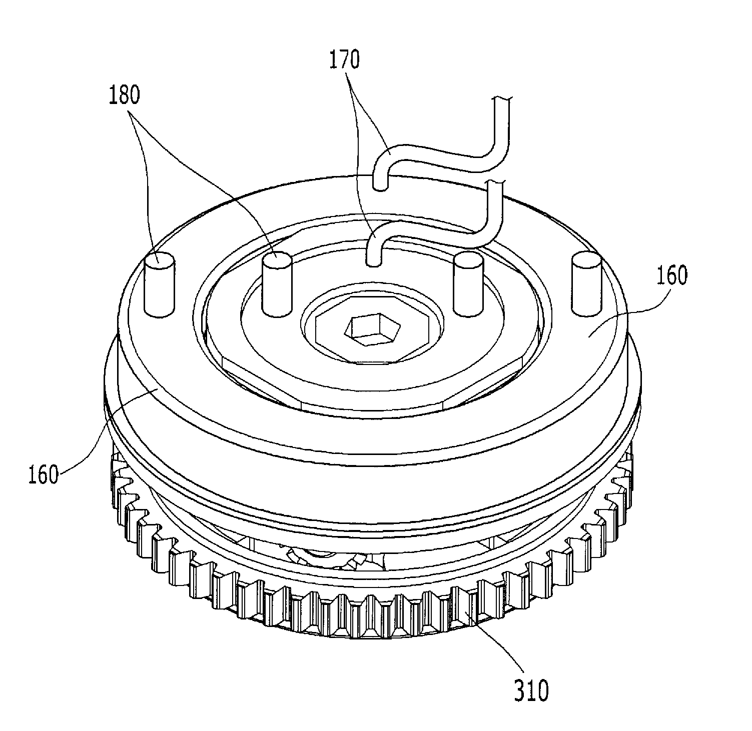
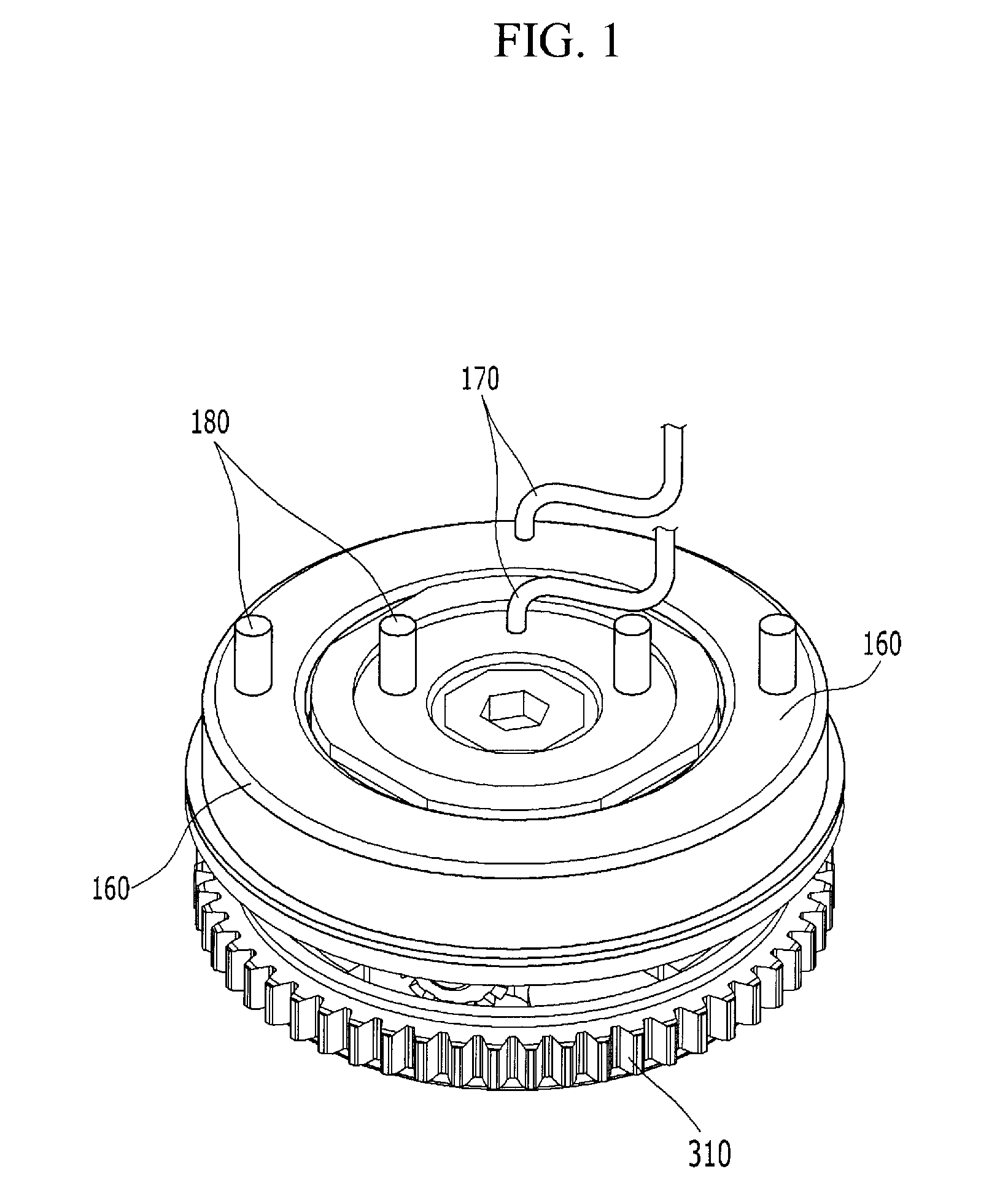
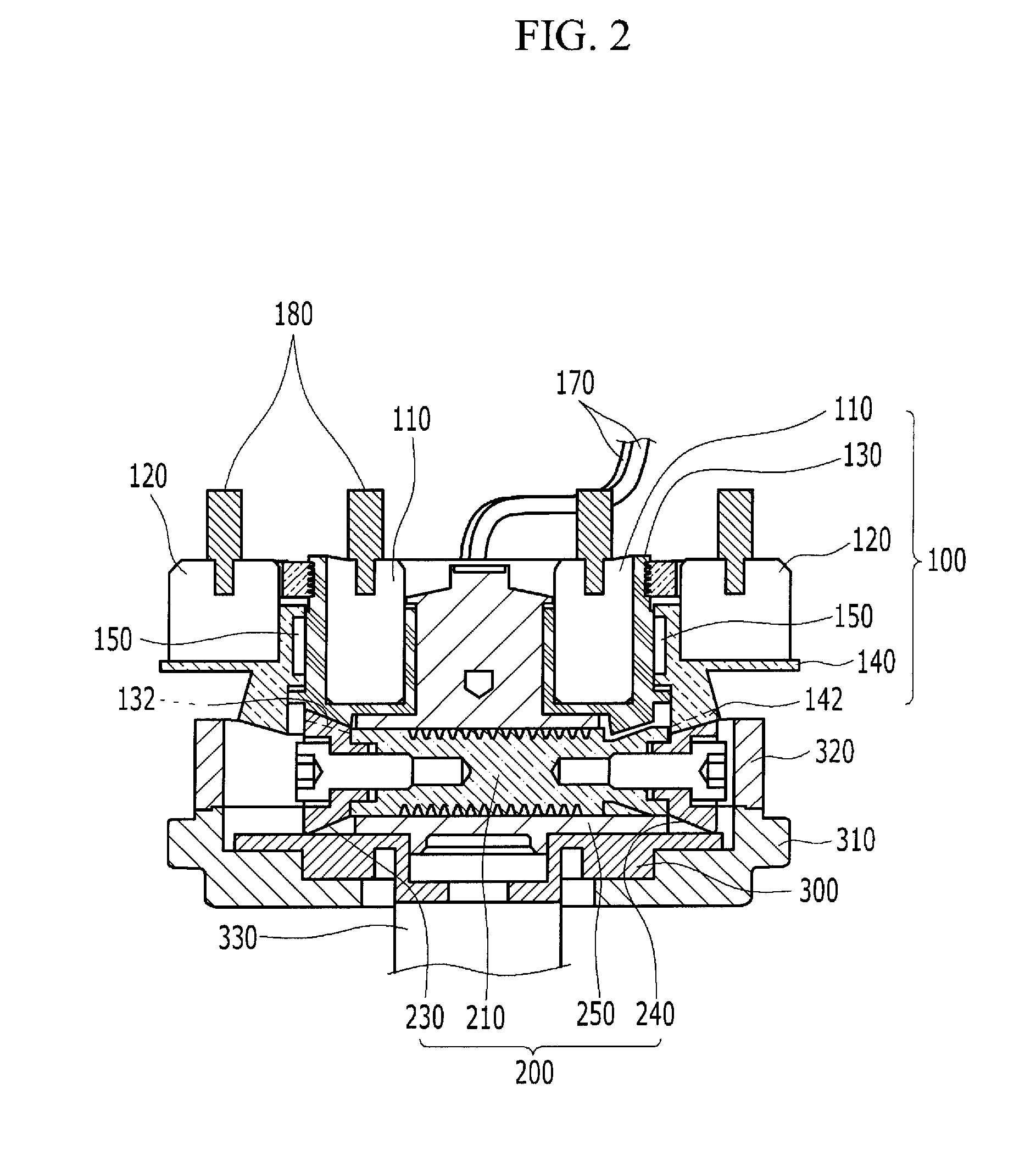
[0035]FIG. 1 is a perspective view of a continuously variable valve timing apparatus according to an exemplary embodiment of the present invention, and FIG. 2 is a cross-sectional view of a continu...


PUM


Abstract

A continuously variable valve timing apparatus may include an end plate connected to a camshaft, a drive sprocket rotating the end plate, a first friction plate disposed to be coaxial to the end plate, a second friction plate disposed to be coaxial to the end plate, a first brake selectively braking the first friction plate, a second brake selectively braking the second friction plate, and a control gear portion which changes relative phase between the end plate and the drive sprocket according to braking of the first friction plate or the second friction plate.

Description

CROSS-REFERENCE TO RELATED APPLICATION[0001]The present application claims priority to Korean Patent Application No. 10-2010-0057205 filed in the Korean Intellectual Property Office on Jun. 16, 2010, the entire contents of which is incorporated herein for all purposes by this reference.BACKGROUND OF THE INVENTION[0002]1. Field of the Invention[0003]The present invention relates to a continuously variable valve timing apparatus. More particularly, the present invention relates to a continuously variable valve timing apparatus which may adjust the timing of the opening and closing of valves.[0004]2. Description of Related Art[0005]Generally, a continuously variable valve timing apparatus (CVVT or Camshaft phaser) is a device which may adjust the timing of the opening and closing of valves.[0006]A general continuously variable valve timing apparatus, usually used in vehicle makers, i.e. a vane-type variable valve timing apparatus, needs relatively small volume and is economical.[0007]T...

Claims


Application Information

Patent Timeline
Patent Type & Authority Applications(United States)
IPC IPC(8): F01L1/34
CPCF01L1/352Y10T74/19828
Inventor KONG, JIN KOOKWOO, SOO HYUNGKIM, JIN SOONKIM, SANG WON
Owner HYUNDAI MOTOR CO LTD
Why Eureka
Try Eureka