System for cooling a circuit of a first fluid of a turbomachine

Active Publication Date: 2019-10-10
SAFRAN +1
View PDF0 Cites 1 Cited by
  • Summary
  • Abstract
  • Description
  • Claims
  • Application Information

AI Technical Summary

Benefits of technology

The patent text describes a system for cooling an oil circuit in an airplane. The system includes a refrigerant fluid circuit, which is smaller in size and lighter than traditional cooling systems, reducing the impact on the airplane's weight. The system also includes a third heat exchanger that dissipates the heat of the oil during the airplane's cruising flight, resulting in energy savings.

Problems solved by technology

In order to ensure significant amounts of heat exchange, such a heat exchanger needs to present a large area, and it therefore presents weight and size that are large.
Unfortunately, such heat exchangers are relatively heavy and they have the disadvantage of disturbing the air stream.
This disturbance has the effect of increasing the aerodynamic drag of the turbomachine and consequently of increasing the energy consumption of the turbomachine; it therefore penalizes the overall efficiency of the turbomachine (i.e. there is an increase in its specific fuel consumption (SFC)).
Whatever the technology used for air and oil heat exchangers, they therefore give rise to head losses in the flow passage for the secondary stream from which the air is drawn, thereby reducing the efficiency of the turbomachine with an increase in its specific fuel consumption (SFC).
The gains obtained by such a thermodynamic device in terms of reducing the head losses induced by the heat exchangers are nevertheless offset by the cost of the energy associated with supplying the power needed to operate the compressor of the thermodynamic device, and by the cost of the energy associated with the weight added by the various components of the heat pump.

Method used


Image

  • System for cooling a circuit of a first fluid of a turbomachine

Examples


Embodiment Construction

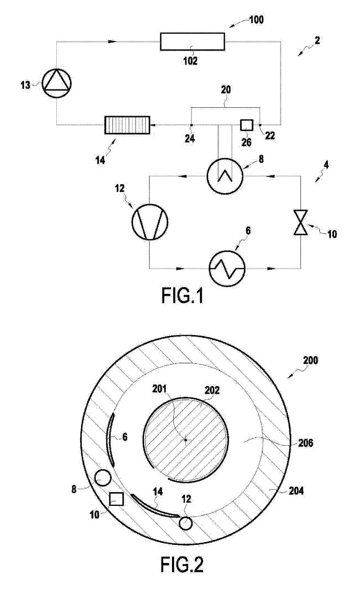
[0047]The invention applies to dissipating any type of heat power generated in a turbomachine and that needs to be removed.

[0048]The example described below relates more particularly to dissipating the heat power generated by heating the oil of an oil circuit 100 in a turbomachine 200. Nevertheless, the system of the invention could equally well apply in any other gas turbine engine to dissipating heat powers coming from the heating of various electrical components, e.g. batteries or electricity generators.

[0049]In known manner, the oil circuit 100 of a turbomachine includes various pieces of equipment 102 that make use of cooling and / or lubricating oil, such as rolling bearings (in particular for turbine and compressor shafts), gearboxes (such as the accessory drive gearbox), electricity generators, etc.

[0050]The oil circuit also includes recovery pumps for recirculating oil from the equipment back to an oil tank, feed pumps, and one or more filters.

[0051]The turbomachine 200 also ...


PUM


Abstract

A cooling system for cooling a circuit of a first fluid of a turbomachine, the cooling system including a refrigerant fluid circuit including a first heat exchanger for exchanging heat between the refrigerant fluid and air, a second heat exchanger for exchanging heat between the refrigerant fluid and the first fluid, an expander located downstream from the first heat exchanger and upstream from the second heat exchanger in the flow direction of the refrigerant fluid, and a compressor located downstream from the second heat exchanger and upstream from the first heat exchanger; the cooling system further includes a third heat exchanger of the first fluid and air type.

Description

FIELD OF THE INVENTION[0001]The present invention relates to the general field of dissipating heat power generated in a turbomachine. It relates in particular to cooling a fluid contained in a circuit, such as an oil circuit, in an airplane turbomachine.STATE OF THE ART[0002]In known manner, a turbomachine includes an oil circuit for lubricating and / or cooling equipment, such as in particular rolling bearings or gear members.[0003]The oil flowing in the oil circuit of the engine is typically cooled by air and oil type heat exchangers, also known as air cooled oil coolers (ACOCs).[0004]These heat exchangers operate by means of a stream of air that is usually drawn from the flow passage of the secondary stream through the turbomachine and that is guided along a circuit for exchanging heat with the oil circuit. Such heat exchangers may be of the “surface” type, where they are in the form of a metal surface piece allowing oil to circulate into channels machined at its center. Heat is th...

Claims


Application Information

Patent Timeline
IPC IPC(8): F01M5/00F02C7/06
CPCF05D2260/213F02C9/18F02C7/224F01M5/002F02C7/06F02C7/14F02C7/16F02C7/185F05D2260/98F05D2210/14Y02T50/60F16N39/02
Inventor MAALOUF, SAMERJALJAL, NAWALDUMOULIN, PIERRETAUVERON, NICOLAS
Owner SAFRAN
Why Eureka
Try Eureka