Artificial lift system

a technology of artificial lifts and lifts, applied in the direction of fluid removal, sealing/packing, borehole/well accessories, etc., can solve the problems of limiting the natural gas production rate and not adding energy to the fluids

Inactive Publication Date: 2011-12-22
BULLEN TERRY
View PDF3 Cites 25 Cited by
  • Summary
  • Abstract
  • Description
  • Claims
  • Application Information

AI Technical Summary

Benefits of technology

[0014]In another aspect, the invention comprises a control system for an artificial lift system comprising a gas pump having a surface fill valve, a pressure actuated fill valve and a bleed valve, the control system comprising a logic controller comprising:

Problems solved by technology

Finding the location of the desirable reservoirs and drilling the wells present their own unique challenges.
Typically fluids in a liquid phase cause the most problems when attempting to move the fluids vertically up the wellbore.
These methods do not add energy to the fluids in the well bore, and therefore are not considered artificial lift systems; however, they do optimize the use of the energy that the reservoir and fluids provide.
These liquids, if not removed from the wellbore, will significantly limit the natural gas production rates as wells as the ultimate recovery of the natural gas reserves.

Method used


Image

  • Artificial lift system
  • Artificial lift system
  • Artificial lift system

Examples


Embodiment Construction

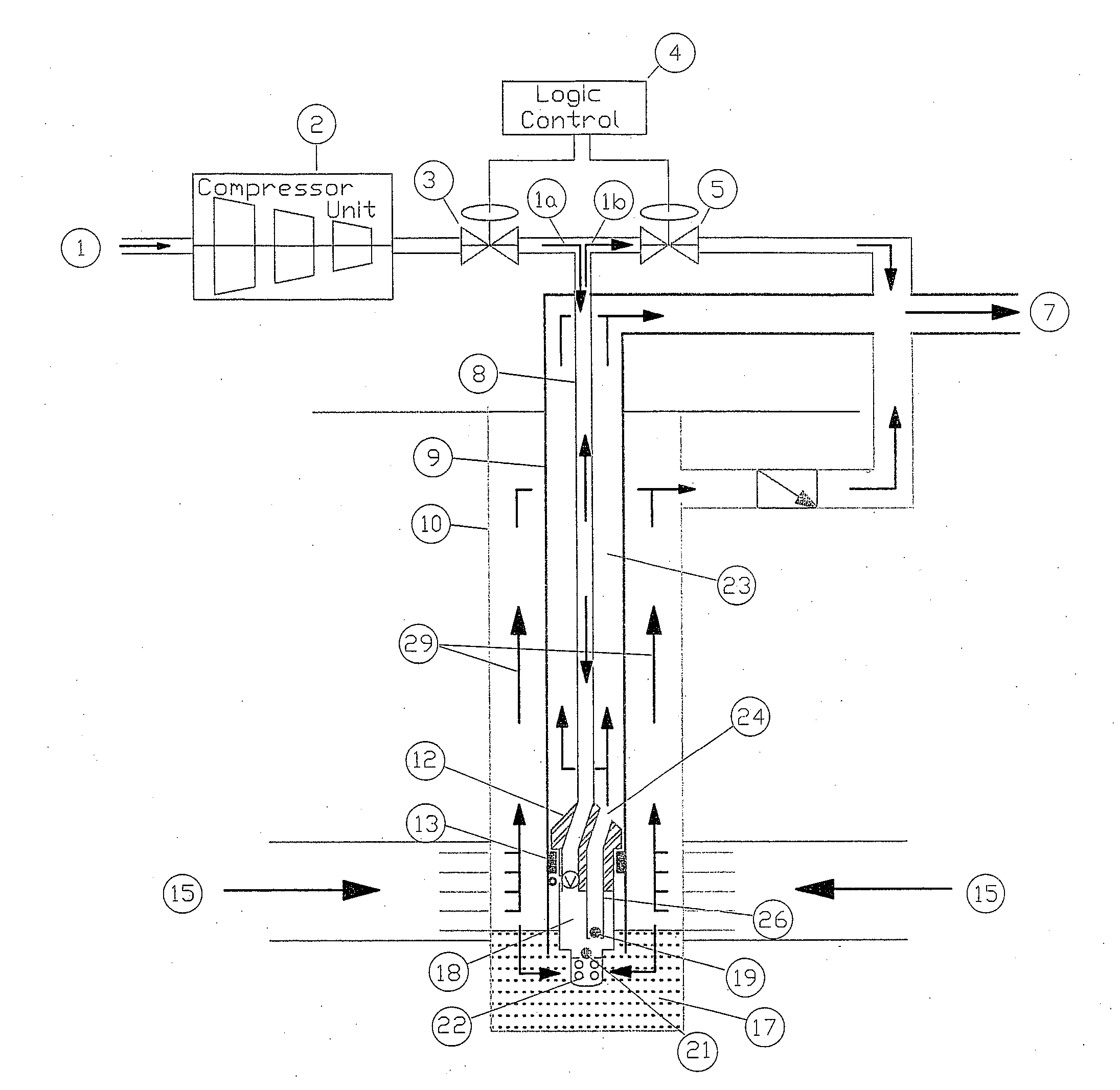
[0025]The invention relates to an artificial lift system, and a system and method of controlling the same. When describing the present invention, all terms not defined herein have their common art-recognized meanings. To the extent that the following description is of a specific embodiment or a particular use of the invention, it is intended to be illustrative only, and not limiting of the claimed invention. The following description is intended to cover all alternatives, modifications and equivalents that are included in the spirit and scope of the invention, as defined in the appended claims.

[0026]In the claims, the word “comprising” is used in its inclusive sense and does not exclude other elements being present. The indefinite article “a” before a claim feature does not exclude more than one of the feature being present.

[0027]Co-owned U.S. Pat. No. 7,717,181, issued on May 18, 2010, describes an artificial lift system, and methods of installing and removing an artificial lift sy...


PUM


Abstract

An artificial lift system provides an artificial lift design specifically for the pumping of liquids from natural gas wells, but not limited to this application. In doing so, production rates and reserves recovered can be significantly increased. The artificial lift system uses small diameter continuous tubing to run the pump in the hole and deliver small volumes of high pressure dry gas as a power fluid to the pump. This power fluid forces liquid that has been drawn into the pump from the bottom of the wellbore to surface. By removing the liquids from the wellbore the natural gas can flow unrestricted to surface. A control system for the artificial lift system delivers a pre-determined volume of power fluid to the pump on a periodic basis. Feedback mechanisms may adjust the volume and/or the period to improve the efficiency of the pump.

Description

BACKGROUND OF THE INVENTION[0001]Subterranean wells have been drilled primarily to produce one or more of the following desired products for example fluids such as water, hydrocarbon liquids and hydrocarbon gas. There are other uses for wells but these are by far the most common. These desired fluids can exist in the geologic layers to depths in excess of 5,000 m below the surface and are found in geological traps called reservoirs where they may accumulate in sufficient quantities to make their recovery economically viable. Finding the location of the desirable reservoirs and drilling the wells present their own unique challenges. Once drilled, the wellbore of the well must be configured to transport safely and efficiently the desired fluid from the reservoir to surface.[0002]Whether or not the desired fluid can reach surface without aid is a function of numerous variables, including: potential energy of the fluid in the reservoir, reservoir driver mechanisms, reservoir rock charac...

Claims


Application Information

Patent Timeline
Patent Type & Authority Applications(United States)
IPC IPC(8): E21B43/00
CPCE21B43/129E21B43/121
Inventor BULLEN, TERRY
Owner BULLEN TERRY
Why Eureka
Try Eureka