Continuous Circulating Sub for Drill Strings

a sub and sub technology, applied in the direction of drilling pipes, drilling casings, borehole/well accessories, etc., can solve the problems of ecd loss during hooking, increase in bottomhole pressure, kicks and losses in the annulus,

Inactive Publication Date: 2011-12-22
DUAL GRADIENT SYST
View PDF2 Cites 45 Cited by
  • Summary
  • Abstract
  • Description
  • Claims
  • Application Information

AI Technical Summary

Benefits of technology

[0005]The present disclosure provides a system and method for maintaining continuous flow through a drill string during drill pipe connection. The system provides a continuous circulation sub having an elongated sub housing with an internal flow path formed in the interior of the housing between first and second ends. A flow port is formed in the housing wall between the first and second ends. The ends of the housing are preferably threaded so that the housing can be attached to drill pipe. A sleeve is slidingly disposed in the interior of the sub housing, and is axially movable from a closed position in which the flow port is blocked, to an open position, in which the flow port is in communication with the internal flow path. The sleeve has a pressure surface defined on it so that fluid pressure applied to the pressure surface will urge the sleeve from the closed position to the open position. A biasing member is provided to urge the valve sleeve to the closed position. Finally, a valve is disposed along the internal flow path, wherein the valve is movable between a first position so as to permit flow along the flow path between said first and second ends of the sub housing and a second position in which flow between the two ends is interrupted. When the sleeve is in the closed position, the valve is in the first position so that mud flows between the first and second ends. When the sleeve is in the open position, the valve is in the second position such that mud flow in through the sub can be maintained during a hook to the first end.

Problems solved by technology

One drawback to the method of the prior art is the loss of equivalent circulating density (ECD) during a hook.
In other words, when mud is being circulated, because of friction in the annulus as the mud is pumped, there is an increase in bottomhole pressure.
The ECD is an important parameter for drilling operations because loss or a drop in ECD can result in kicks and losses in the annulus.
The need to stop drilling fluid circulation in the drill string in order to make drill string connections is time consuming and disruptive to drilling operations.

Method used


Image

  • Continuous Circulating Sub for Drill Strings
  • Continuous Circulating Sub for Drill Strings
  • Continuous Circulating Sub for Drill Strings

Examples


Embodiment Construction

[0016]In the detailed description of the invention, like numerals are employed to designate like parts throughout. Various items of equipment, such as fasteners, fittings, etc., may be omitted to simplify the description. However, those skilled in the art will realize that such conventional equipment can be employed as desired.

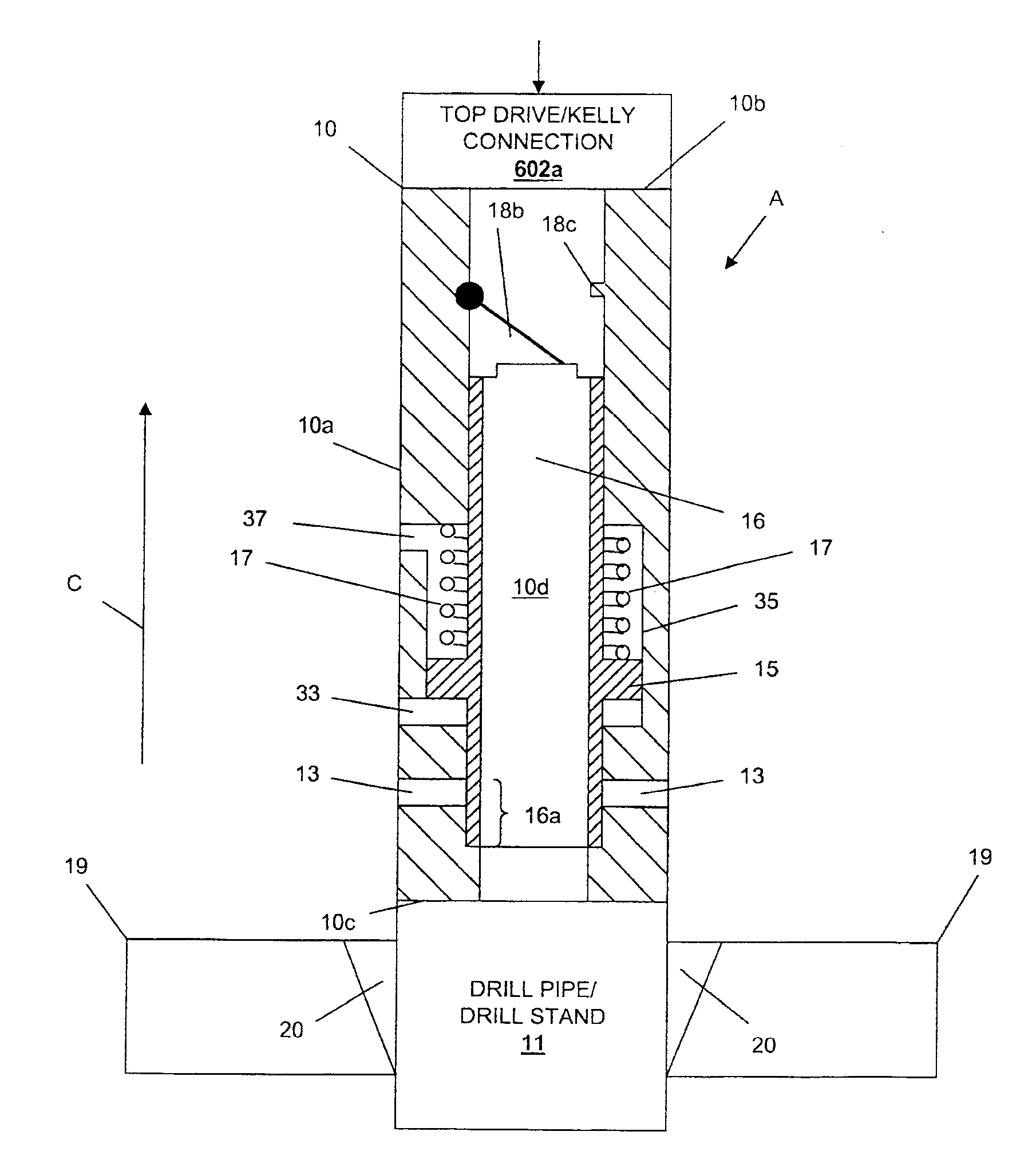
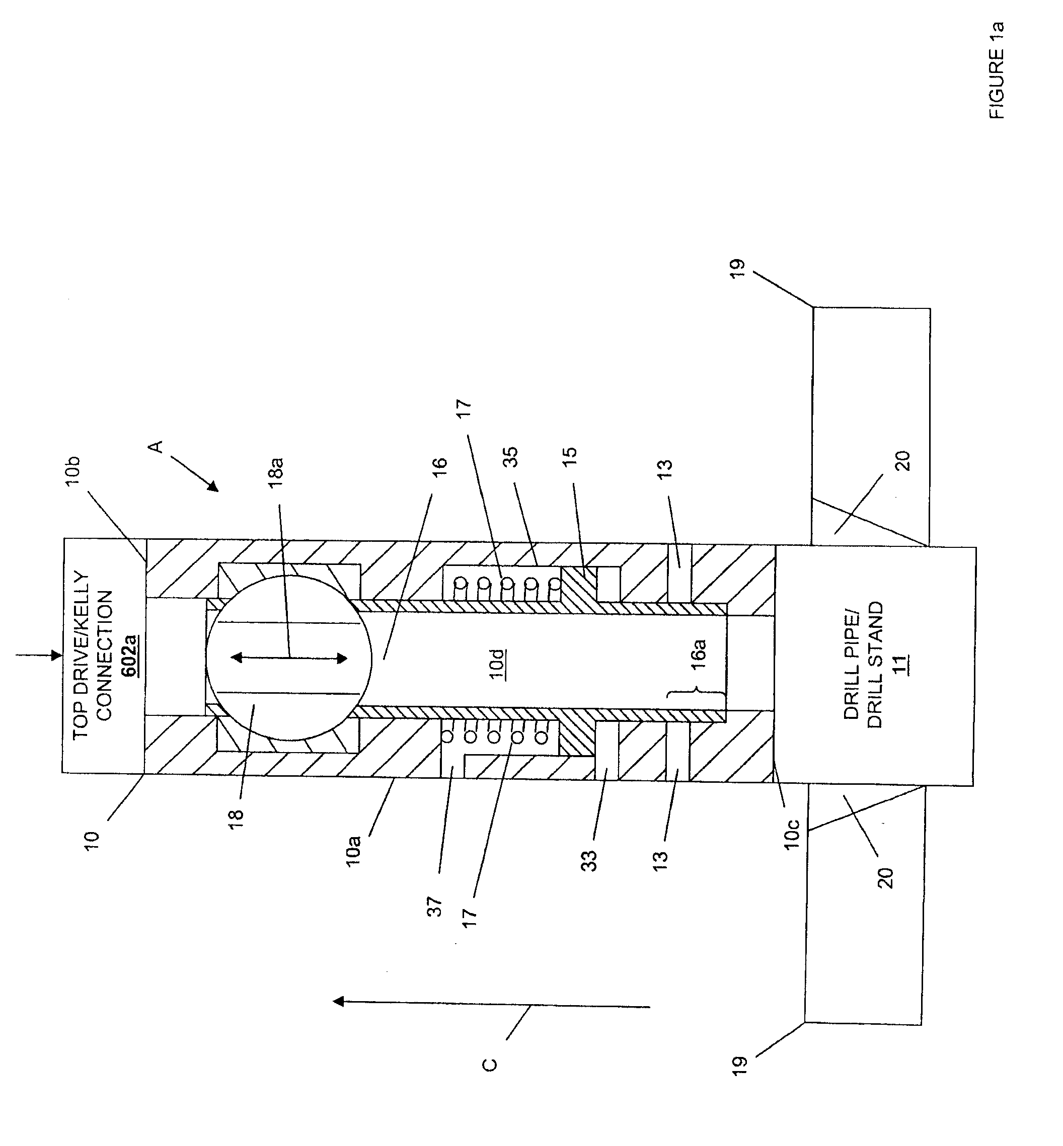
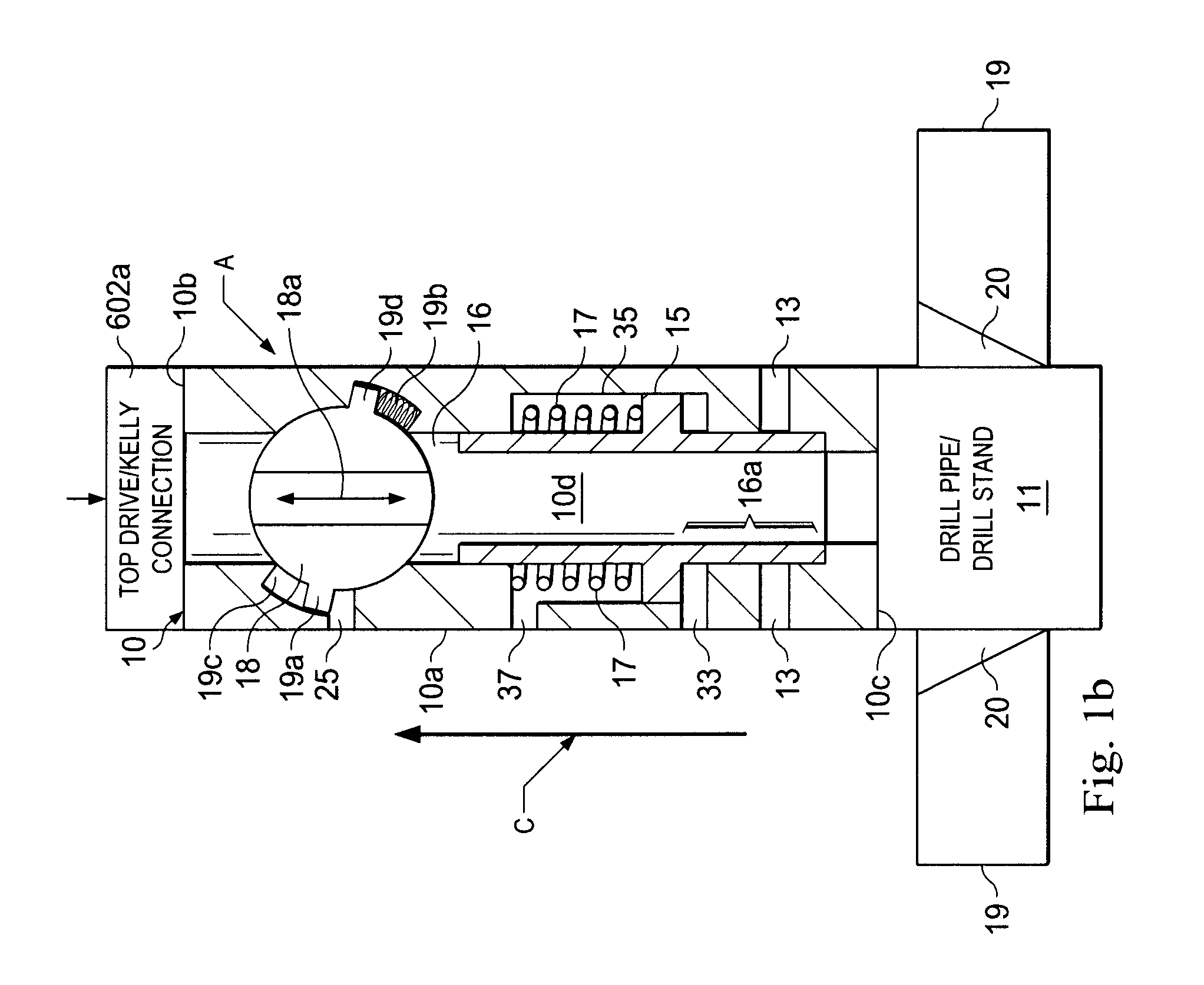
[0017]Referring now to FIGS. 1 and 2, one embodiment of a continuous circulation sub (CCS) 10 is illustrated. The CCS of the present disclosure provides for the continuous circulation of drilling fluid (e.g., drilling mud) through a drill string while making drill string connections / hooks on a rig floor. The continuous circulation of drilling fluid through a drill string allows the ECD to be maintained in the drill string annulus during a drill string connection or hook.

[0018]The CCS 10 of the present disclosure may operate in a number of modes, including a top circulation mode A, illustrated in FIG. 1 a, and a drill string connection / hook circulation mode B t...


PUM


Abstract

A system and method for maintaining continuous flow through a drill string during drill pipe connection includes establishing drilling fluid flow axially through the length of a tubular sub attached to the top of a drill string. The sub is then engaged with a collar disposed at least partially around the perimeter of the sub so as to define an exterior flow path along the exterior of the sub. Radial flow is then initiated into the sub through said collar and along said exterior flow path. Axial flow is then terminated through the length of the tubular sub while maintaining radial flow into the sub. A pipe joint is then attached to the top of the tubular sub, axial flow is reestablished through the length of the tubular sub, radial flow is terminated into the sub, and the collar is disengaged from the sub.

Description

CROSS REFERENCE[0001]The present application claims priority to U.S. Provisional Application Ser. No. 61 / 356,441, attorney docket number 44379.46, filed on Jun. 18, 2010, the disclosure of which is incorporated herein by reference in its entirety.BACKGROUND[0002]In the drilling of oil and gas wells, drilling fluid such as, for example, a variety of drilling muds known in the art, is conventionally pumped through the drill string via a connection at the top of the drill string in order to circulate the drilling fluid through the drill string during drilling operations. The drilling fluid is typically held in drilling fluid tanks or reservoirs and pumped from a stand pipe to a Kelly drive or top drive, which in turn is connected to the top of the drill string. As drilling progresses during the drilling process, portions of drill pipe are added (e.g., as 90 ft stands, 30 ft individual pipe sections, and / or a variety of other drill string sizes known in the art) between the top drive an...

Claims


Application Information

Patent Timeline
Patent Type & Authority Applications(United States)
IPC IPC(8): E21B7/00E21B21/06
CPCE21B17/00E21B21/106E21B19/16
Inventor DEBOER, LUC
Owner DUAL GRADIENT SYST
Why Eureka
Try Eureka