Torque link with shimmy damper

a technology of damper and torque link, which is applied in the direction of alighting gear, transportation and packaging, skis/runners, etc., can solve the problems of not being economical to redesign and replace the landing gear, affecting the stiffness of the landing gear, and affecting the performance of the landing gear

Active Publication Date: 2011-12-22
THE BF GOODRICH CO
View PDF6 Cites 5 Cited by
  • Summary
  • Abstract
  • Description
  • Claims
  • Application Information

AI Technical Summary

Benefits of technology

[0007]A torque link for an aircraft landing gear system incorporates a spring-damper system that includes a pair of cooperating arms. One arm may take the form of a structural, load carrying member, such as a beam, and the other arm may take the form of a damper assembly. The arms are located between a clevis portion and a lug portion of the torque link. The load carrying member cooperates with the damper assembly to allow some deformation that can be damped out by the damper assembly. In one embodiment, the damper assembly may be bottomed out when subjected to excessive loads and then operate as rigid, structural link between the clevis and lug portions. The torque link may advantageously provide a dual role as a structural torque link as well as shimmy damping system.

Problems solved by technology

Wheel shimmy can be caused by a number of conditions such as low torsional stiffness, excessive freeplay in the landing gear, wheel imbalance, or worn parts.
Often, however, wheel shimmy occurs even in new aircraft due to resonance between the landing gear and the airframe of the aircraft.
Solving a shimmy problem after an aircraft is built presents challenges because it is not usually economical to redesign and replace the landing gear in order to solve the problem.
Plus increasing landing gear stiffness can typically only be accomplished with a significant weight increase.
Such designs require frequent maintenance, and temperature increases can reduce damping efficiency.
Further, such shimmy dampers generally do not permit 360 degree rotation of the wheel or wheels and typically are difficult to adjust to provide different levels of damping.
While such a shimmy damper may be functionally adequate, it is not readily retrofittable to existing landing gear assemblies and installation and / or removal of the belleville spring washers typically requires the landing gear to be substantial disassembled, as many of these types of dampers require the spring washers to be telescoped over the landing gear strut.
This method is not an option for main landing gears which do not employ steering actuation.

Method used


Image

  • Torque link with shimmy damper
  • Torque link with shimmy damper
  • Torque link with shimmy damper

Examples


Embodiment Construction

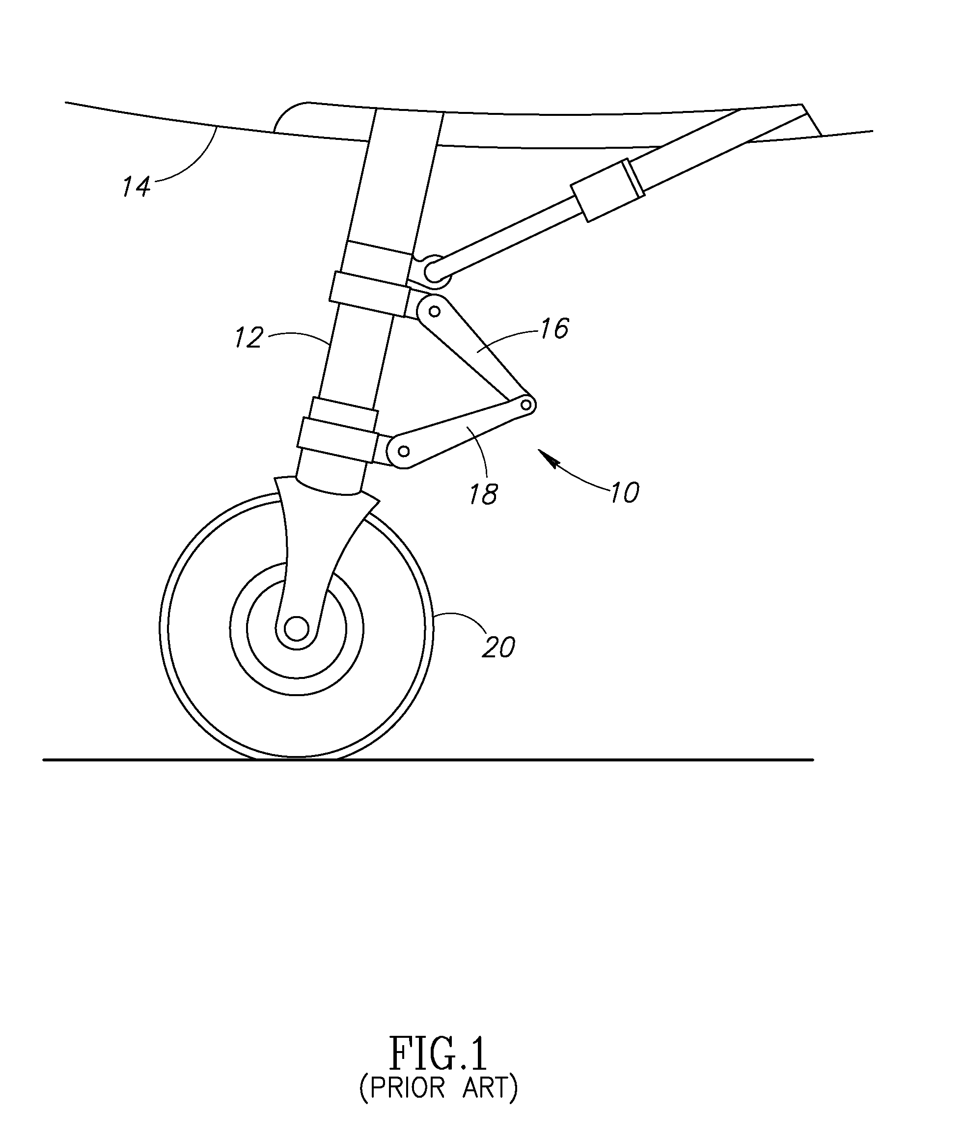
[0021]In the following description, certain specific details are set forth in order to provide a thorough understanding of various embodiments of the invention. However, one skilled in the art will understand that the invention may be practiced without these details. In other instances, well-known structures associated with aircraft, aircraft landing gear systems, torque links or torque links, and damping mechanisms along with the operation thereof have not necessarily been shown or described in detail to avoid unnecessarily obscuring descriptions of the embodiments of the invention.

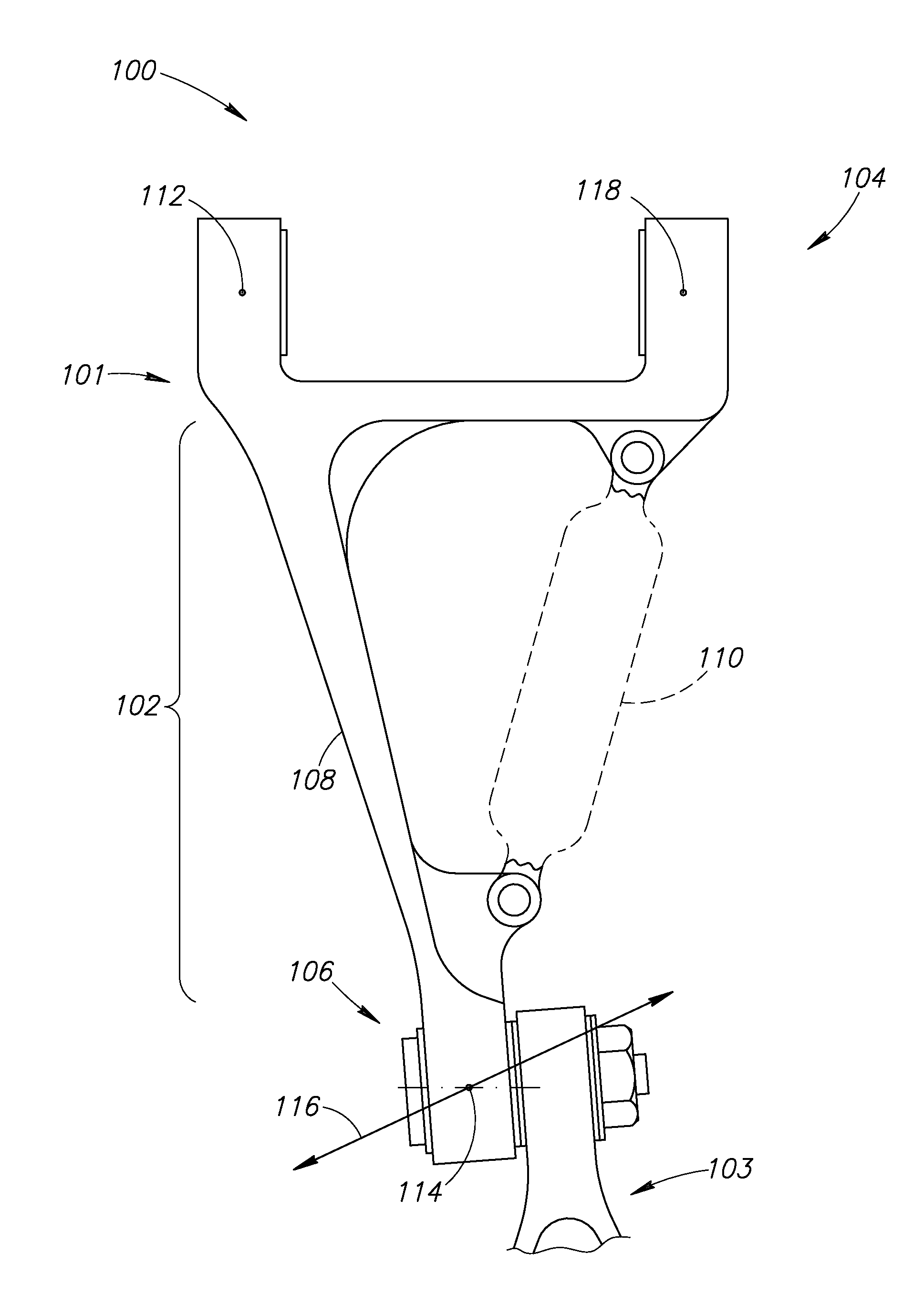
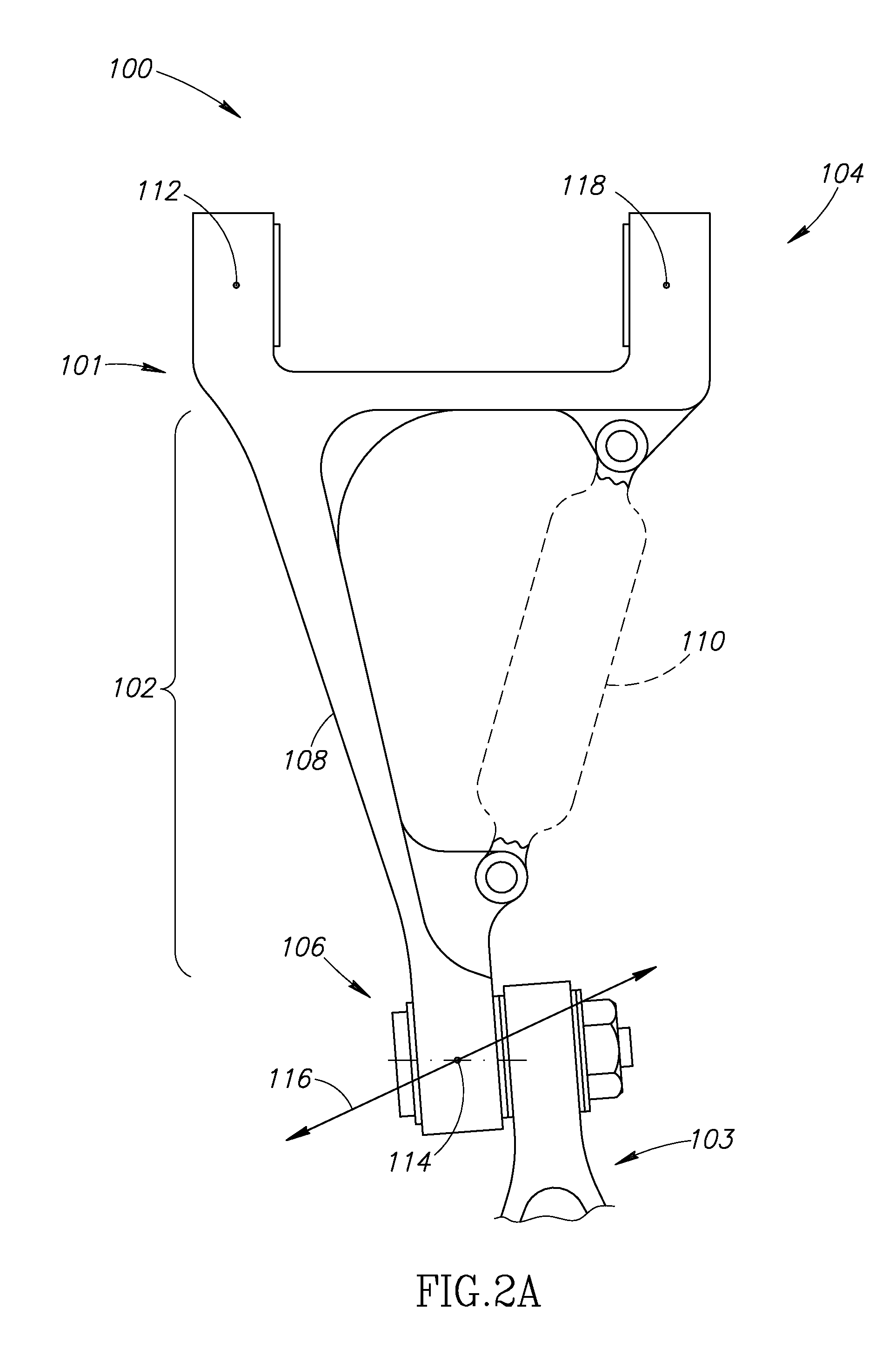
[0022]The following description generally relates to a torque link, also referred to as a torque arm, having a spring-damper system structurally incorporated into the design and functionality of the torque link. The spring portion may take the form of a structurally rigid beam while the damping portion may take the form of a damping mechanism or assembly, and where each portion functions as a structural ...


PUM


Abstract

A torque link includes a spring-damper system structurally incorporated into the design and functionality of the torque link. The spring portion may take the form of a structurally rigid beam while the damping portion may take the form of a damping mechanism or assembly. The damping mechanism is configured to damp out deformations in the beam and also configured to bottom out and become a structural tension / compression member when the load through the torque link exceeds a threshold load. The method damping may take a number of forms, such as, but not limited to, solid media damping, fluid damping with or without an orifice, a hydraulic or magnetic circuit, coulomb damping, etc.

Description

FIELD OF THE INVENTION[0001]This invention relates to a torque link for a landing gear system, and more specifically a torque having a shimmy damper mechanism.BACKGROUND OF THE INVENTION[0002]As shown in FIG. 1, a torque link assembly 10 attaches to a landing gear system 12 of an aircraft 14. The torque link assembly 10 includes an upper torque link 16 and a lower torque link 18. As illustrated, the torque link assembly 10 provides a connection between an upper landing gear strut and a lower piston. Because the piston can rotate freely in the strut, a wheel 20 mounted to it needs to be held firm to keep the aircraft rolling in a straight line. Conversely, when taxiing at low speed, say, on lineup or landing rollout, this wheel can be used to steer the aircraft 14 while on the ground. The torque link assembly 10 keeps the piston in line with the strut and, when connected to an actuator, permits controlled steering of aircraft 14 on the ground.[0003]Wheel shimmy is a condition in whic...

Claims


Application Information

Patent Timeline
Patent Type & Authority Applications(United States)
IPC IPC(8): B64C25/50
CPCB64C25/505
Inventor LUCE, WILLIAM E.
Owner THE BF GOODRICH CO
Why Eureka
Try Eureka