Continuous dipole antenna

a dipole antenna and dipole technology, applied in the direction of subaqueous/subterranean adaption, insulation, borehole/well accessories, etc., can solve the problems of inability to use drill and refinement methods in the extraction of standard crude oil, inability to achieve thermal gradients in heated materials, and inefficient spacing of electrodes/antenna

Active Publication Date: 2011-12-22
HARRIS CORP
View PDF9 Cites 34 Cited by
  • Summary
  • Abstract
  • Description
  • Claims
  • Application Information

AI Technical Summary

Problems solved by technology

Because of the extremely high viscosity of bituminous ore, oil sands, oil shale, tar sands, and heavy oil, the drilling and refinement methods used in extracting standard crude oil are typically not available.
Heating subsurface heavy oil bearing formations by prior RF systems has been inefficient due to traditional methods of matching the impedances of the power source (transmitter) and the heterogeneous material being heated, uneven heating resulting in unacceptable thermal gradients in heated material, inefficient spacing of electrodes / antennae, poor electrical coupling to the heated material, limited penetration of material to be heated by energy emitted by prior antennae and frequency of emissions due to antenna forms and frequencies used.

Method used


Image

  • Continuous dipole antenna
  • Continuous dipole antenna
  • Continuous dipole antenna

Examples


Embodiment Construction

[0029]The subject matter of this disclosure will now be described more fully, and one or more embodiments of the invention are shown. This invention may, however, be embodied in many different forms and should not be construed as limited to the embodiments set forth herein. Rather, these embodiments are examples of the invention, which has the full scope indicated by the language of the claims.

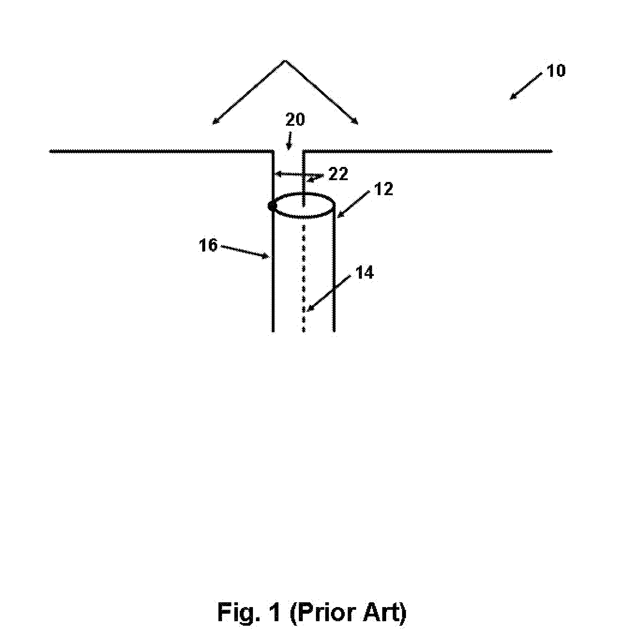
[0030]FIG. 1 is a representation of a typical prior art dipole antenna. Prior art antenna 10 includes a coaxial feed 12, which in turn includes an inner conductor 14 and an outer conductor 16. Each of these conductors is connected at one end to a dipole antenna section 18 via a feed line 22. The other ends of conductors 14 and 16 are connected to an alternating current power source (not shown). Unshielded gap or break 20 between dipole antenna sections 18 forms a driving discontinuity that results in radio frequency transmission. Oil well piping is generally unsuited for use as a conventional ...


PUM


Abstract

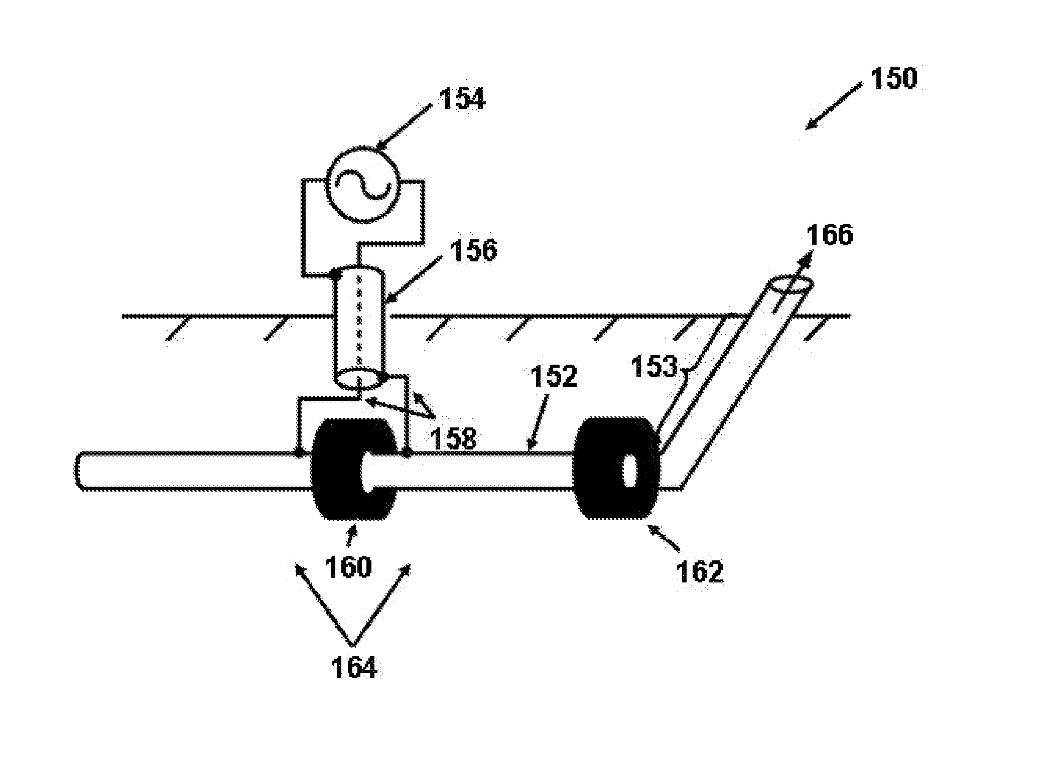
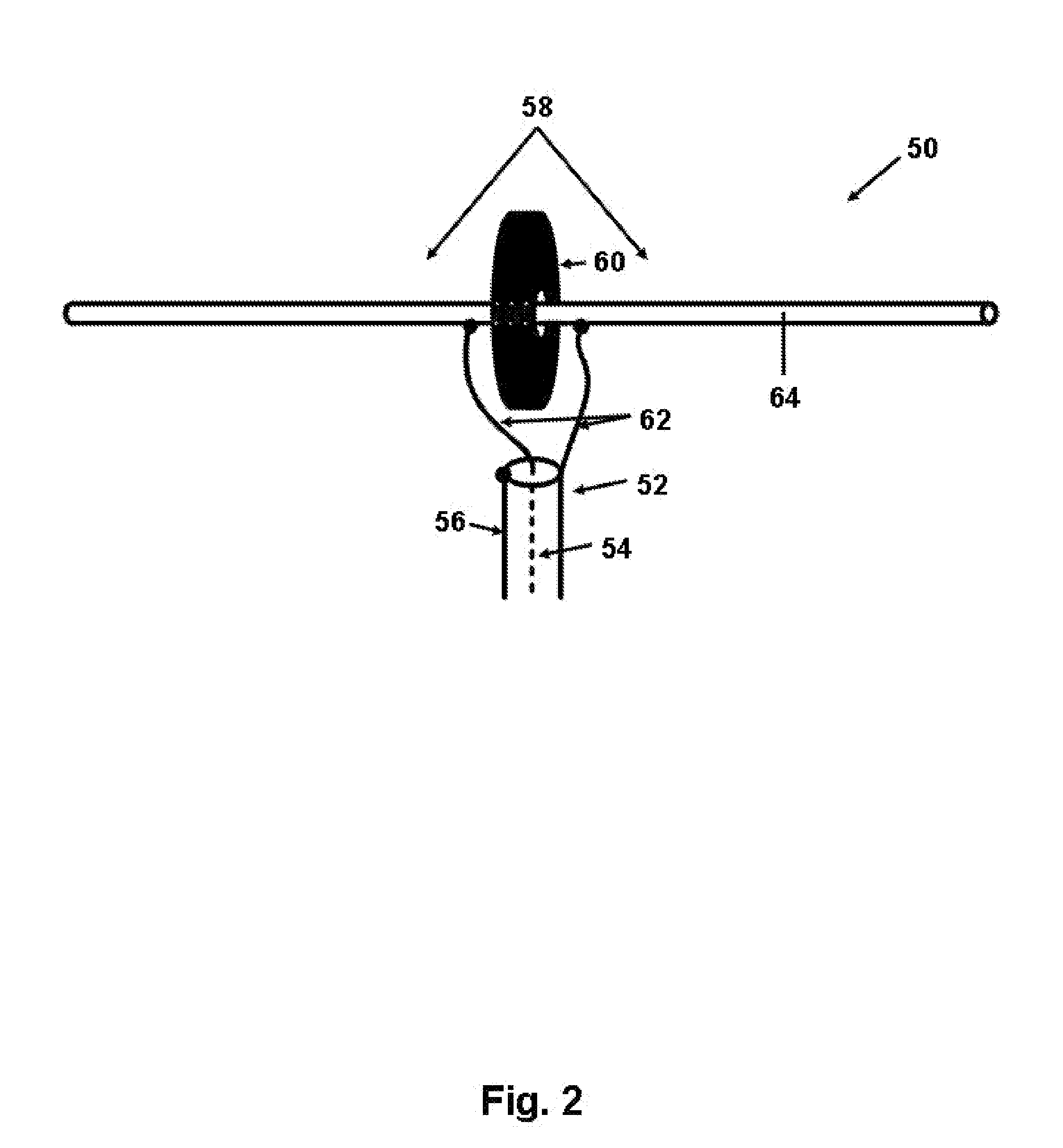
A dipole antenna may be created by surrounding a portion of the continuous conductor with a nonconductive magnetic bead, and then applying a power source to the continuous conductor across the nonconductive magnetic bead. The nonconductive magnetic bead creates a driving discontinuity without requiring a break or gap in the conductor. The power source may be connected or applied to the continuous conductor using a variety of preferably shielded configurations, including a coaxial or twin-axial inset or offset feed, a triaxial inset feed, or a diaxial offset feed. A second nonconductive magnetic bead may be positioned to surround a second portion of the continuous conductor to effectively create two nearly equal length dipole antenna sections on either side of the first nonconductive magnetic bead. The nonconductive magnetic beads may be comprised of various nonconductive magnetic materials, and preformed for installation around the conductor, or injected around the conductor in subsurface applications. Electromagnetic heating of hydrocarbon ores may be accomplished.

Description

STATEMENT REGARDING FEDERALLY SPONSORED RESEARCH OR DEVELOPMENT[0001][Not Applicable]CROSS REFERENCE TO RELATED APPLICATIONS[0002]This specification is related to Harris Corporation docket number GCSD-2298 (Attorney Docket Number 22927US01) filed on or about the same date as this specification, which is incorporated by reference here.BACKGROUND OF THE INVENTION[0003]The present invention relates to radio frequency (“RF”) antennas. In particular, the present invention relates to an advantageous apparatus and method for using a continuous conductor, such as oil well piping, as a dipole antenna to transmit RF energy for heating.[0004]As the world's standard crude oil reserves are depleted, and the continued demand for oil causes oil prices to rise, oil producers are attempting to process hydrocarbons from bituminous ore, oil sands, tar sands, and heavy oil deposits. These materials are often found in naturally occurring mixtures of sand or clay. Because of the extremely high viscosity ...

Claims


Application Information

Patent Timeline
Patent Type & Authority Applications(United States)
IPC IPC(8): H01Q9/16
CPCE21B36/04E21B43/2401E21B43/2408H01Q9/16H01Q1/04H01Q1/44E21B43/305
Inventor PARSCHE, FRANCIS EUGENE
Owner HARRIS CORP
Why Eureka
Try Eureka