Calibration of large camera networks

a directional sensor and camera network technology, applied in the field of directional sensor network calibration, can solve the problems of inability to scale to larger networks, inaccurate single processor methods, and limitations of aforementioned calibration methods, and achieve the effect of robustness of any dynamic reconfiguration and efficient calibration of a large camera network

Inactive Publication Date: 2011-12-22
PURDUE RES FOUND INC +1
View PDF1 Cites 42 Cited by
  • Summary
  • Abstract
  • Description
  • Claims
  • Application Information

AI Technical Summary

Benefits of technology

[0011]The present invention provides for the efficient calibration of a large camera network in terms of both communications and computations, as well as the robustness of any dynamic reconfiguration. In other words, the present invention solves the scalability problem of camera calibration. More specifically, when the number of cameras increases, the communications and computations required for camera calibration ac

Problems solved by technology

This single processor method is accurate when calibrating small networks (e.g., having less than 50 sensors) but is not suitable when scaled to larger networks (e.g., having more than 50 sensors).
This distributed localization algorithm allows for localization of a static network, but will not operate in a dynamic network where the image features required for localization are not already present.
The aforementioned calibration methods all have limitations, such as requiring human interaction during the calibration process or imposing constraints on the positioning of the cameras to satisfy calibration algorithm requirements, by way of example.
Furthermor

Method used


Image

  • Calibration of large camera networks
  • Calibration of large camera networks
  • Calibration of large camera networks

Examples


third embodiment

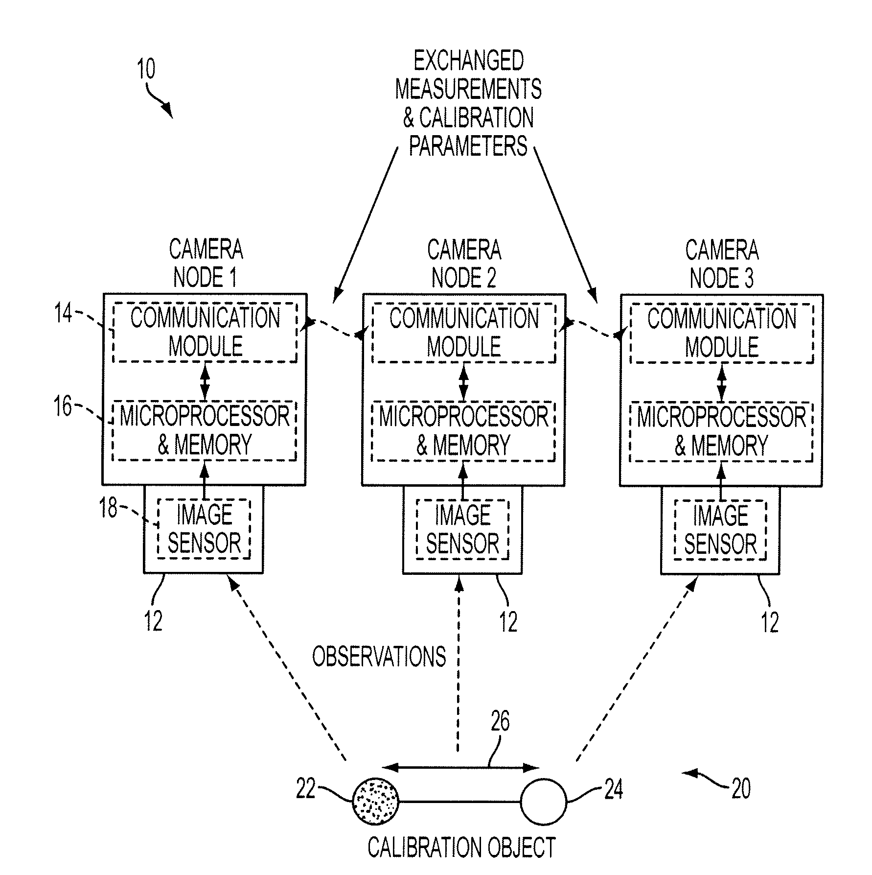
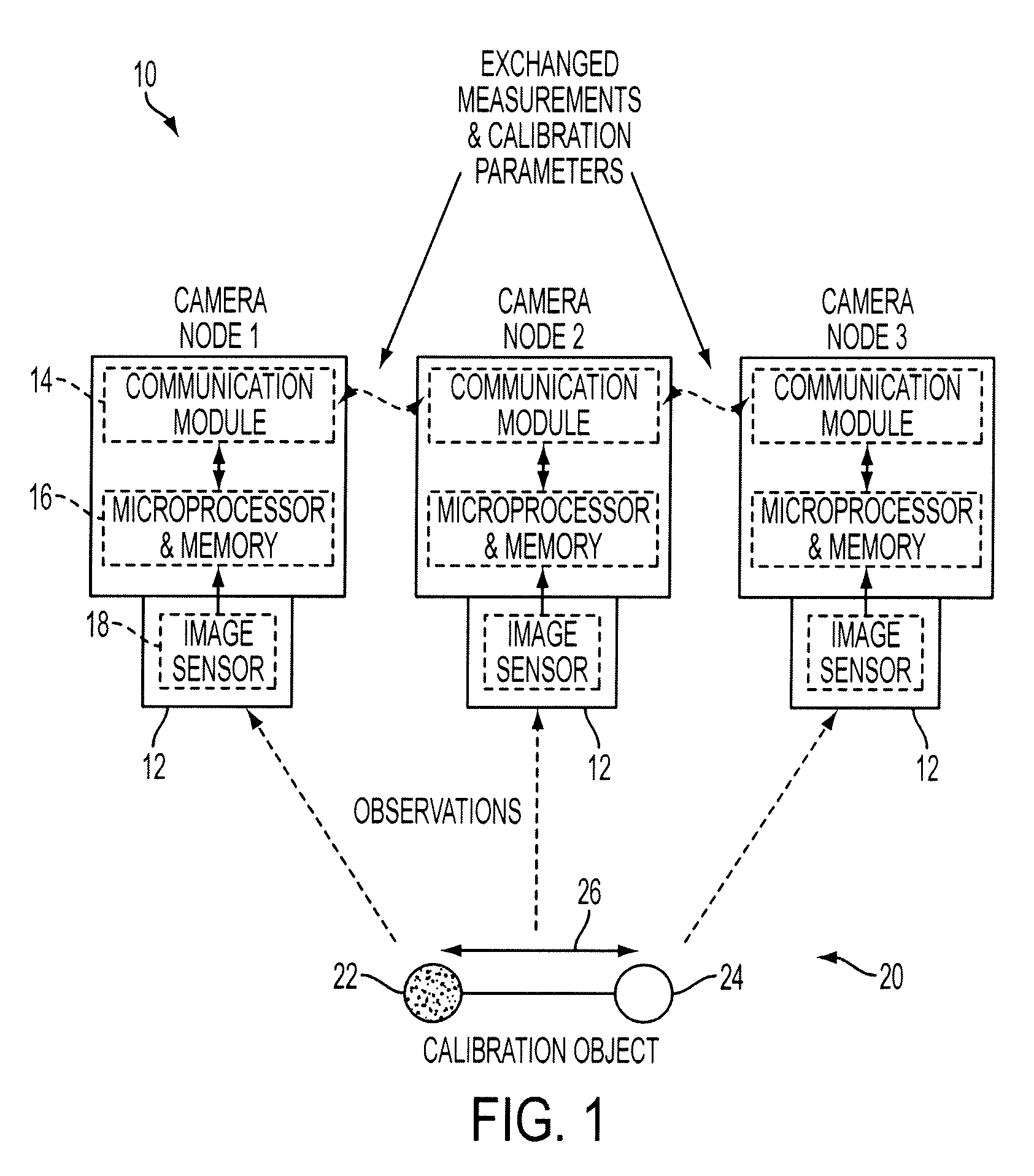
During this accuracy evaluation procedure (whenever a new estimate is produced), the camera node 12 may compute the total difference between the currently estimated parameters with respect to its neighbors (pti,k) and the previously estimated parameters (pt-1i,k) and compare this total difference to a predefined threshold (ε). It will be appreciated that other evaluation criterion may used to determine whether a given level of accuracy had been achieved by a camera node 12, in other embodiments. Furthermore, while the third embodiment involves the performance of the accuracy evaluation procedure by each camera node 12, it is also contemplated that each camera node 12 may transmit information to a user interface 72, which may then perform some or all of the accuracy evaluation procedure.

[0091]One advantage of this illustrative embodiment is that the accuracy evaluation step allows each individual camera node 12 to decide as to whether it has concluded its own calibration procedure. A...

fourth embodiment

[0093]The camera nodes 12 in the fourth illustrative embodiment include similar modules 40-48 to those described above with reference to FIG. 7, but further include a user interaction module 74, as illustrated in FIG. 17. The function of the user interaction module is to communicate with the user interface 72 to receive instructions regarding the calibration of the network 10 and to provide information regarding the calibration performance of one or more camera nodes 12 to the human operator 70. In some embodiments, this information may include the calibration accuracy computed for the camera node 12 by the estimate integration module 48, or some indication thereof. The process 80 performed by the user interaction module 74, in conjunction with the other module 40-48 of the camera node 12, is presented as a flowchart in FIG. 18. This interactive calibration process 80 of the fourth embodiment allows the camera nodes 12 of the network 10 to provide calibration-related feedback to the...


PUM


Abstract

The present disclosure relates to a sensor network including a plurality of nodes, each node having a directional sensor, a communication module, and a processor configured to receive local measurements of a calibration object from the directional sensor, receive additional measurements of the calibration object from neighboring nodes via the communication module, estimate an initial set of calibration parameters in response to the local and additional measurements, receive additional sets of calibration parameters from neighboring nodes via the communication module, and recursively estimate an updated set of calibration parameters in response to the additional sets of calibration parameters. Additional systems and methods for calibrating a large network of camera nodes are disclosed.

Description

CROSS REFERENCE TO RELATED APPLICATIONS[0001]This application claims priority under 35 U.S.C. §119(e) to U.S. Provisional Patent Application Ser. No. 61 / 178,727, filed on May 15, 2009, the entire disclosure of which is expressly incorporated herein by reference.TECHNICAL FIELD[0002]The present disclosure generally relates to the calibration of a directional sensor network. More particularly, the present disclosure relates to systems and methods for calibrating a large network of camera-based sensors.BACKGROUND ART[0003]Calibrating a network of directional sensors may be achieved using a number of techniques. One known technique for calibrating a network of camera-based sensors requires a single, centralized processor which receives image feature data from each of the sensors and then performs a minimization of calibration errors for the entire network. This single processor method is accurate when calibrating small networks (e.g., having less than 50 sensors) but is not suitable whe...

Claims


Application Information

Patent Timeline
IPC IPC(8): H04N17/00H04B17/40
CPCG06T7/0018G06T7/2093H04B17/40H04N9/093H04N17/002H04N5/217G06T7/292G06T7/80
Inventor MEDEIROS, HENRY PONTIPARK, JOHNNYKAK, AVINASHIWAKI, HIDEKAZU
Owner PURDUE RES FOUND INC
Why Eureka
Try Eureka