
Light Fixtures Comprising Organic Light Emitting Diodes

Inactive Publication Date: 2011-12-22
ABL IP HLDG
View PDF14 Cites 12 Cited by
  • Summary
  • Abstract
  • Description
  • Claims
  • Application Information

AI Technical Summary

Benefits of technology

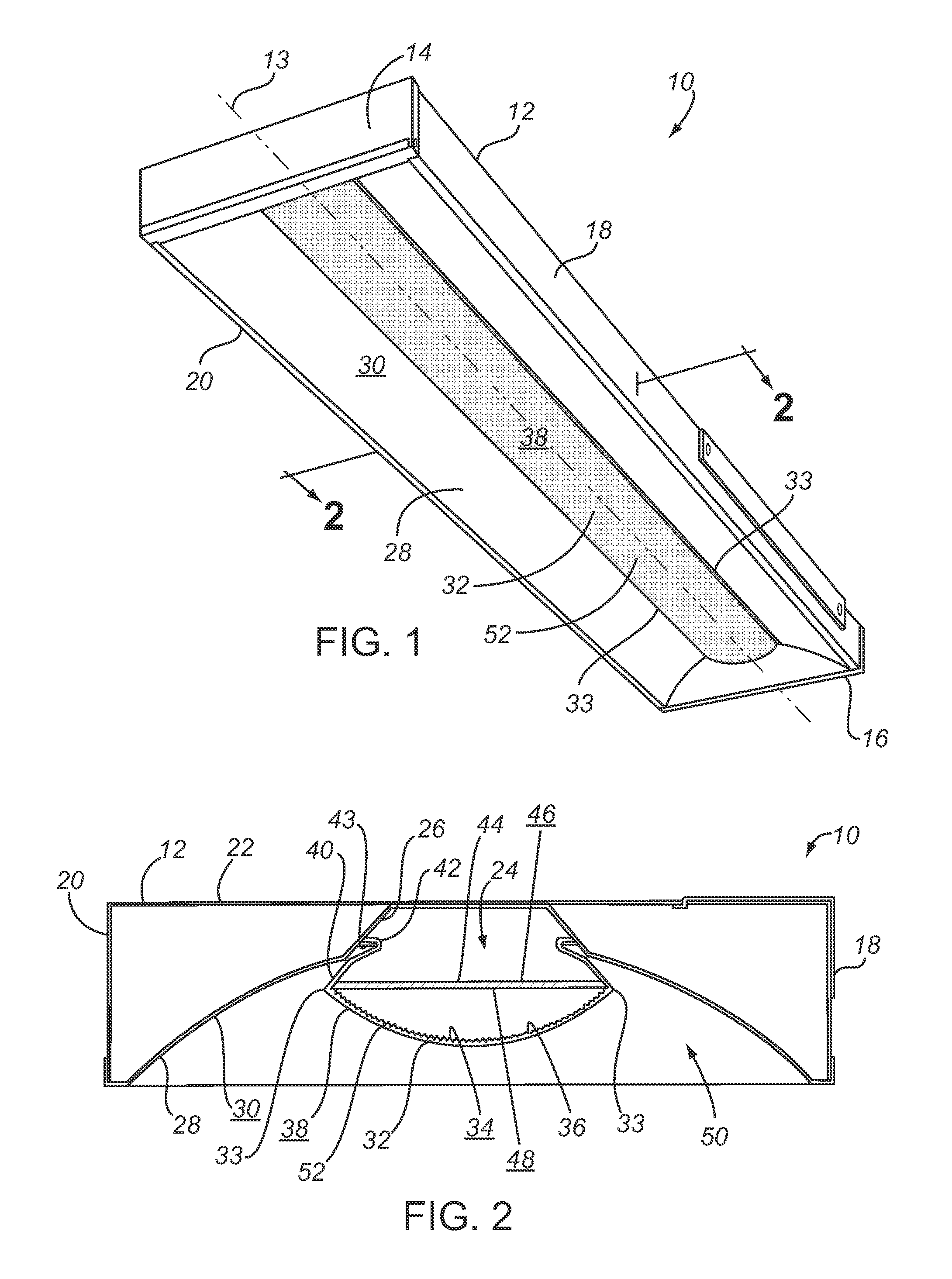
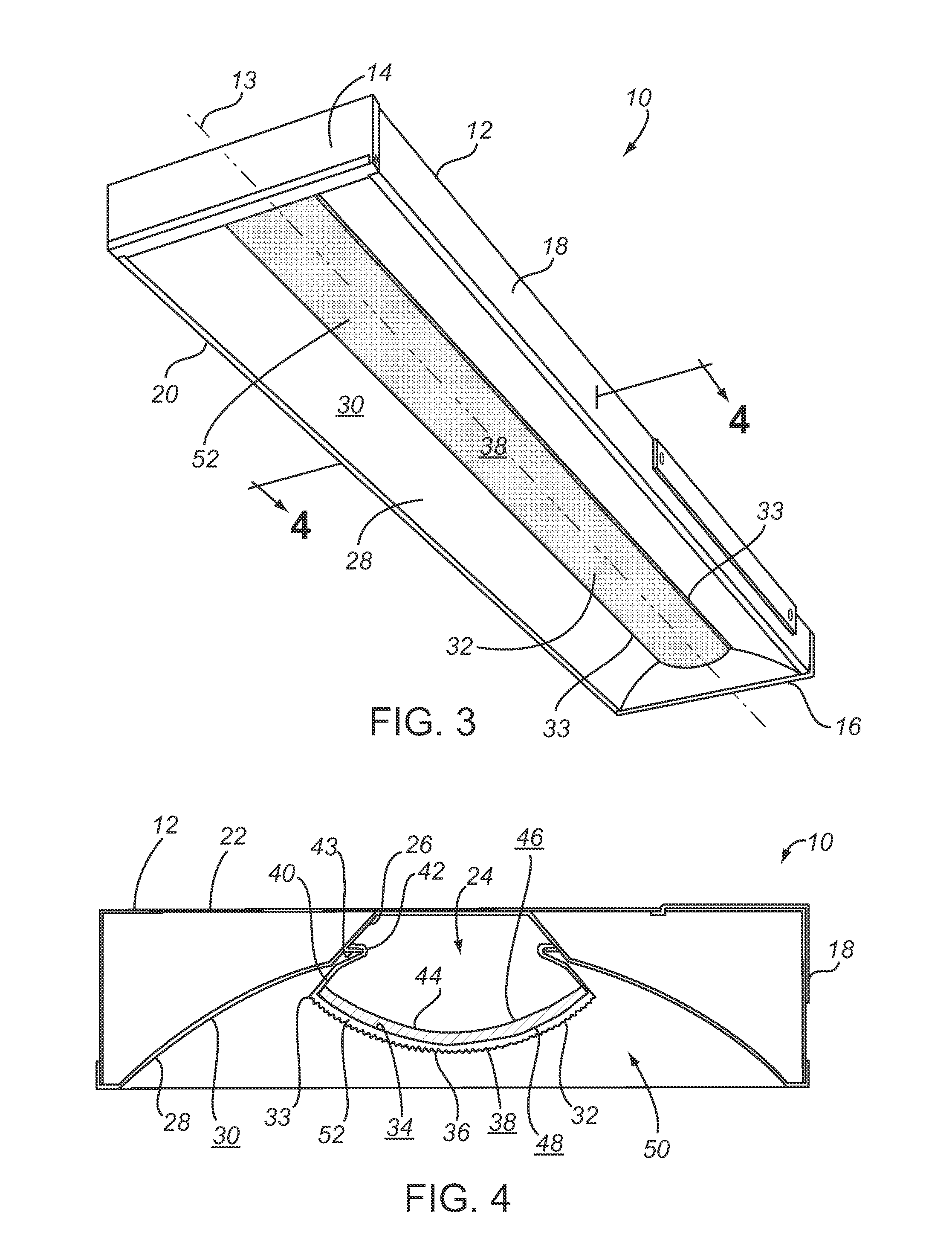
[0009]In one embodiment, the OLED is coupled to the two edges of the optic. Due to the geometry of the optic the OLED is very close to the refractive portion. In another embodiment, the second surface of the OLED is coupled to and contacts the inner surface of the refractive portion. In either embodiment, the OLED is either sufficiently close to or contacting the refractive portion such that surface area of emitted light is maximized. Thus, to an observer it appears as though the refractive portion itself is the light source. Additionally, the OLED is placed sufficiently close to (or within) the intended area that reflected light and optical efficiency are maximized.
[0010]Embodiments of the invention thus provide for improved lighting by providing OLEDs as a light source, and by placing those OLEDs within the light source in a manner that maximizes surface area of the emitted light and also maximizes the amount of reflected light.

Problems solved by technology

But fluorescent lamps have drawbacks as well.
Bright and intense fluorescent lamps may be uncomfortable and may also result in undesirable direct lighting.
“Direct lighting” means that the light is only directed into the space immediately below the light fixture, which leaves other areas of the space dark.
In general, direct lighting may impair the comfort of the illuminated space.
But optics may defeat the advantages of a fluorescent lamp; for example, optics may create distracting changes in brightness level and pattern as seen by a moving observer in the illuminated space.

Method used


Image

  • Light Fixtures Comprising Organic Light Emitting Diodes
  • Light Fixtures Comprising Organic Light Emitting Diodes
  • Light Fixtures Comprising Organic Light Emitting Diodes

Examples


Embodiment Construction

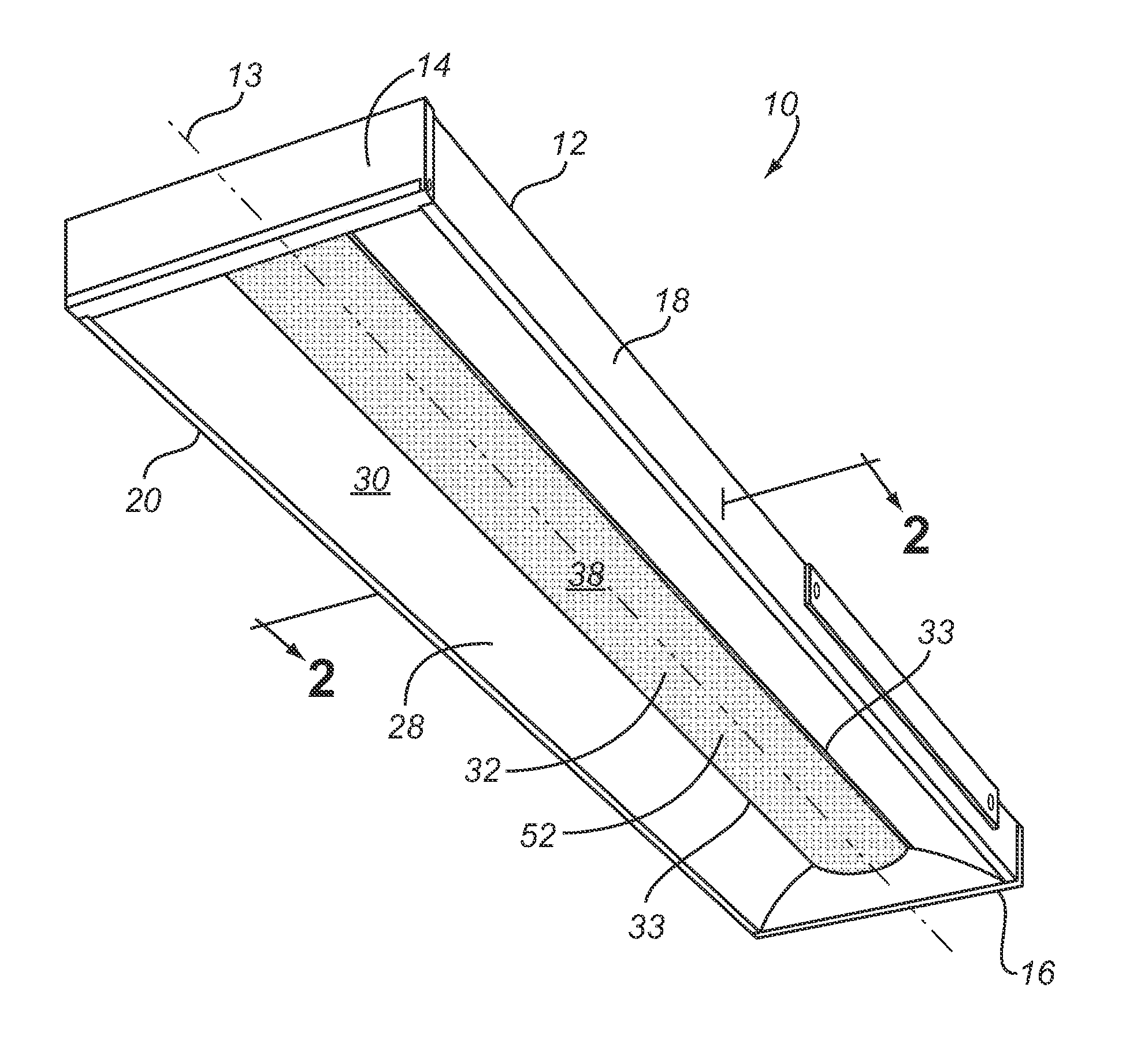
[0018]Certain embodiments of the invention provide a light fixture 10 comprising an organic light emitting diode (OLED) 44 as the light source, and further comprising a housing 12, at least one hollow 28, and an optic 32.

[0019]In certain embodiments of the invention, traditional fluorescent light fixtures commonly known as “RT5” light fixtures may be retro-fitted with an OLED 44. Embodiments of such a light fixture are shown and described in U.S. Pat. No. 7,229,192, which is incorporated herein by reference. Retro-fitting an existing RT5 light fixture may be desirable to reduce manufacturing costs and to retain RT5 fixtures that are already in use. In other embodiments, however, the OLED 44 may be fitted into other types of light fixtures 10, and not necessarily an RT5 light fixture. It should be understood that the light fixtures 10 shown in the figures may represent either a traditional RT5 fixture or any other type of light fixture 10.

[0020]In certain embodiments the housing 12 o...


PUM

PropertyMeasurementUnit
Poweraaaaaaaaaa
Flexibilityaaaaaaaaaa
Areaaaaaaaaaaa

Abstract

Light fixtures comprising an organic light emitting diode (OLED) as the light source, and further comprising a housing, at least one hollow, and an optic. The at least one hollow defines an intended area where light is emitted, and includes a reflective surface to reflect light within the intended area. The optic comprises a refractive portion that is defined by two edges. In one embodiment, the OLED is coupled to the two edges of the optic. In another embodiment, the OLED is coupled to and contacts an inner surface of the refractive portion. In either embodiment, the OLED is either sufficiently close to or contacting the refractive portion such that surface area of emitted light is maximized. Additionally, the OLED is placed sufficiently close to (or within) the intended area that reflected light and optical efficiency are maximized.

Description

FIELD OF THE INVENTION[0001]The invention relates generally to light fixtures, and in particular, to the use of organic light emitting diodes in light fixtures.BACKGROUND OF THE INVENTION[0002]An important consideration in the design of light fixtures is selection of the light source. Fluorescent lamps have long been the light source of choice in many commercial applications, particularly for indoor office lighting. There are many types of fluorescent lamps, such as a linear T8 (1 inch diameter), T12 (1.5 inch diameter), or T5 (⅝inch diameter) lamps manufactured by Osram / Sylvania and others. These fluorescent lamps provide distribution efficiencies and high lumen output, favorable qualities when illuminating a space.[0003]But fluorescent lamps have drawbacks as well. For example, fluorescent lamps have a high lumen output and are very compact—the popular T5 lamp only has a ⅝inch diameter—which results in a high luminous intensity per unit area. Bright and intense fluorescent lamps m...

Claims


Application Information

Patent Timeline
IPC IPC(8): F21V15/01B23P6/00
CPCF21S8/033F21S8/04F21V5/02Y10T29/49716F21V17/04F21Y2105/008Y02B20/36F21V13/04F21Y2105/00F21Y2115/15Y02B20/30
Inventor MAYFIELD, III, JOHN T.QUINLAN, JEFFREY M.MCCANLESS, FORREST S.
Owner ABL IP HLDG
Learn More