
Adjustable dynamic x-ray filter

a dynamic filter and x-ray technology, applied in the field of x-ray imaging, can solve the problems of reducing clinical utility, difficult alignment relative to focal spot, and difficult alignment of anti-scatter grids between patients and image receptors, and achieve the effect of reducing noise and increasing contras

Active Publication Date: 2011-12-22
MILLER ZACHARY A
View PDF2 Cites 9 Cited by
  • Summary
  • Abstract
  • Description
  • Claims
  • Application Information

AI Technical Summary

Benefits of technology

"The present invention is a system and method for determining the location of an x-ray source and adjusting the grid lines in an anti-scatter grid to produce images with increased contrast and reduced noise. The system includes an x-ray source with a source locator, an IR transmitter, and an IR receiver. The source locator uses IR technology to locate the x-ray source and align the grid lines with the ideal x-ray beam path. The grid lines selectively permit the x-ray beams to pass through and align with the ideal path. The system also includes an adjustable x-ray grid with alternating radiopaque and radiolucent material that can be adjusted to align with the x-ray beam emissions. The adjustment means selectively align the x-ray grid lines to permit the passage of the x-ray beam emissions and produce images with increased contrast and reduced noise."

Problems solved by technology

A high grid ratio, while more effective, is also more difficult to align relative to a focal spot.
Since the relative separation of the focal spot and the image receptor is variable, determining the proper position and orientation of an anti-scatter grid between a patient and the image receptor becomes a difficult alignment problem.
Thus while mobile radiography is in many ways more convenient than fixed installation radiography, its clinical utility is diminished due to the inferior image quality caused by scattered radiation.
This is a greater problem in mobile radiography due to the difficulty in producing the proper alignment of the focal spot with the anti-scattering grids.

Method used


Image

  • Adjustable dynamic x-ray filter
  • Adjustable dynamic x-ray filter
  • Adjustable dynamic x-ray filter

Examples


Embodiment Construction

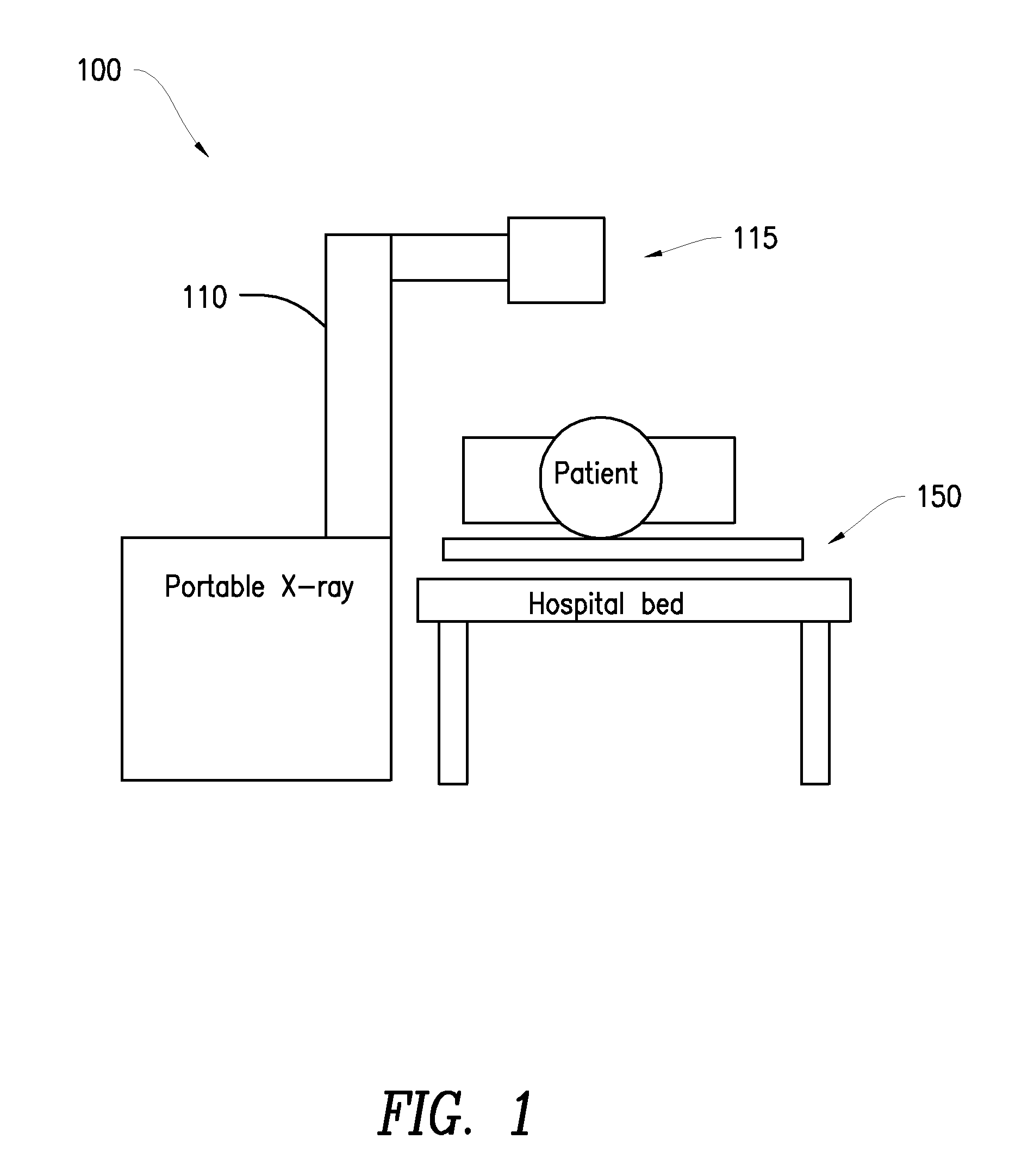
[0018]FIGS. 1 and 3 show a system 100 of the present invention for aligning x-ray emissions from an x-ray machine and for adjusting grid lines in an anti-scatter grid to obtain diagnostic image information with increased contrast and reduced noise due to scattered x-rays. The system 100 includes a portable x-ray machine 110 having an x-ray head 115 and an x-ray plate 150 used to removably receive an x-ray film cassette or digital x-ray detector 155. In one embodiment, a source locator 120 is attached to the housing of x-ray head 115 of x-ray machine 110 and x-ray plate 150 is attached to a flexible filter, anti-scatter grid 160. Both the source locator 120 and the flexible filter, anti-scatter grid 160 are mechanisms used to facilitate the acquisition of images with increased contrast and reduced noise when compared to images obtained using prior art portable x-ray machines and prior art grids.

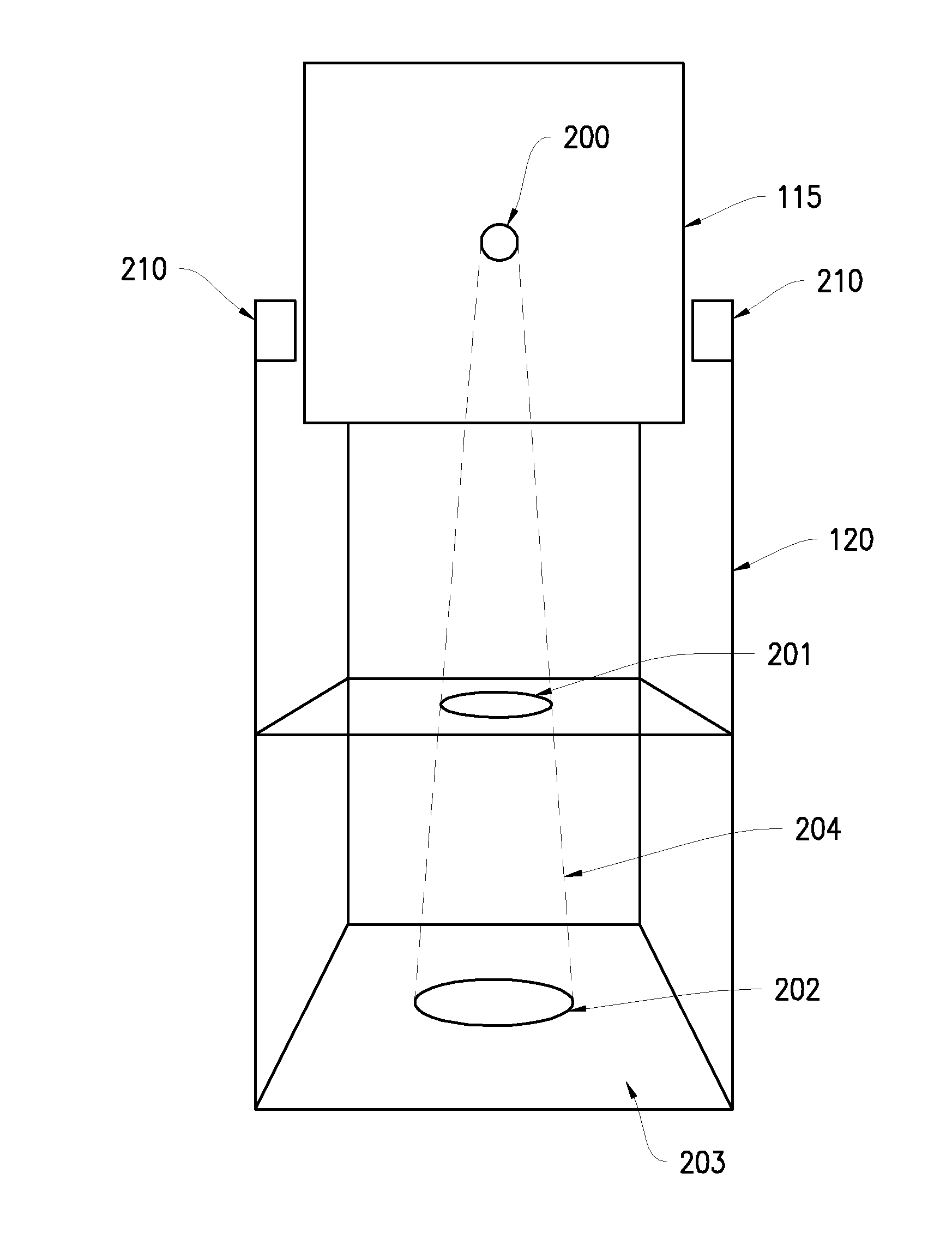
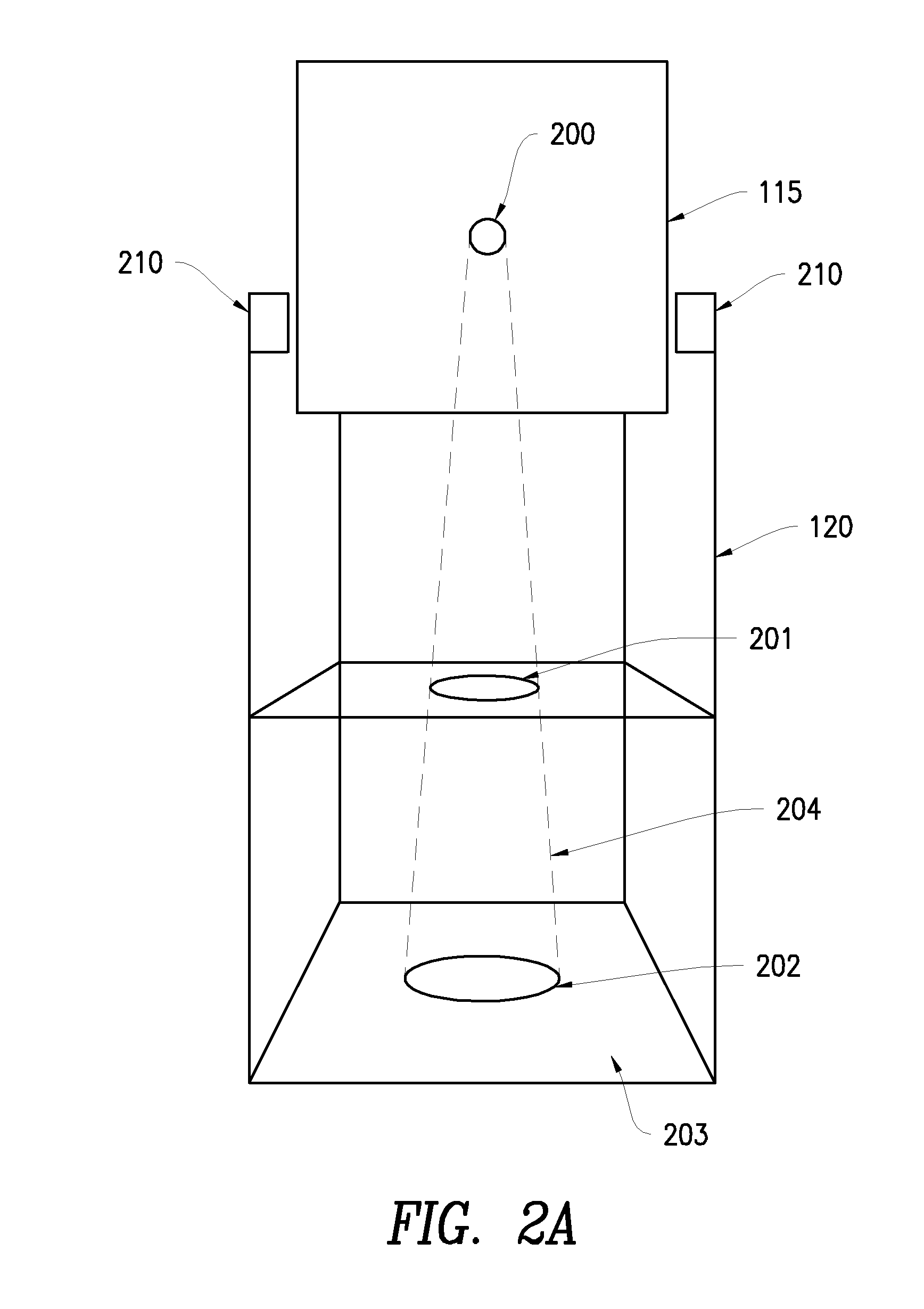
[0019]Referring now to FIG. 2A, there is shown a source locator 120 in greater detail. The...


PUM


Abstract

A system and method for determining the location of an x-ray source of an x-ray machine and adjusting grid lines in an anti-scatter grid are disclosed. An ideal beam path is obtained and is used to adjust grid lines in the anti-scatter grid. In one embodiment, the invention uses a source locator to locate the x-ray source, communicate this location to the said adjustable anti-scatter grid which could align the grid lines mechanically, by means of servos attached to the grid lines, to the ideal x-ray beam path. In other embodiment electrical currents are used to align grid lines with the beam source. By aligning the grid lines with the beam path, images with increased contrast and reduced noise can be produced.

Description

PRIORITY AND RELATED APPLICATION[0001]N / AFIELD OF THE INVENTION[0002]The present invention relates to x-ray imaging, in particular, to alignment systems for portable x-ray imaging devices.BACKGROUND OF THE INVENTION[0003]In a hospital setting, mobile radiographic exams are performed on patients that are incapable of being moved, or are difficult to move. In tertiary care medical centers, mobile radiographic exams represent a significant percentage of the radiographic exams performed. X-rays passing through an object, such as a human body, experience some degree of scatter. The primary x-rays transmitted through an object travel on a straight line path from the x-ray source (also referred to herein as the x-ray focal spot) to the image receptor and carry object density information. Scattered x-rays form a diffuse image that degrades primary x-ray image contrast. In some patients, scattered x-ray intensity exceeds the intensity of primary x-rays. Scattering phenomena is well known and...

Claims


Application Information

Patent Timeline
Patent Type & Authority Applications(United States)
IPC IPC(8): A61B6/08
CPCA61B6/00A61B6/4291A61B6/4411A61B6/4452A61B6/4405A61B6/502A61B6/505A61B6/547A61B6/587A61B6/487A61B6/08
Inventor MILLER, ZACHARY A.
Owner MILLER ZACHARY A
Learn More