Removable long-lived and reusable u-shaped hybrid nut

a hybrid nut, long-lived technology, applied in the direction of screws, threaded fasteners, fastening means, etc., can solve the problems of excessive rigidity of said known nuts, difficult positioning of nuts, and still suffer from a number of drawbacks, so as to improve the rigidity of nuts, improve the elastic behavior, and facilitate mounting

Active Publication Date: 2011-12-22
ILLINOIS TOOL WORKS INC
View PDF25 Cites 24 Cited by
  • Summary
  • Abstract
  • Description
  • Claims
  • Application Information

AI Technical Summary

Benefits of technology

[0012]In particular, the retaining claw allows easy insertion of a tool, such as the tip of a screwdriver, which is able to slacken the retaining pressure of the clip nut on the panel, thereby allowing easy removal thereof.
[0013]A nut according to the present invention, owing to its constructional configuration, also has an improved elastic behavior which has the effect of making it easier to perform mounting thereof on the panel and improving the rigidity of the nuts according to the prior art.
[0014]Finally, the provision of its anti-torsion mechanism ensures an improved performance compared to the prior art upon tightening of the screw.

Problems solved by technology

It must be said that, despite the results achieved by the prior art, it still suffers from a number of drawbacks.
For example, generally speaking, there exists the aforementioned problem of excessive rigidity of said known nuts.
This consists in the great difficulty of arranging them in position and the practical impossibility of removing them from the panel once they have performed their function or have deteriorated or become obsolete.
Another existing drawback at present is the specialized nature of said type of nuts resulting from the limited range of their elastic action.
Owing to the intrinsic constructional nature of the nuts according to the art, they are relatively weak in response to torsional forces which may deform the upper strip and damage the nut.

Method used


Image

  • Removable long-lived and reusable u-shaped hybrid nut
  • Removable long-lived and reusable u-shaped hybrid nut
  • Removable long-lived and reusable u-shaped hybrid nut

Examples


Embodiment Construction

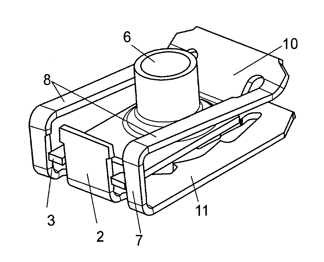
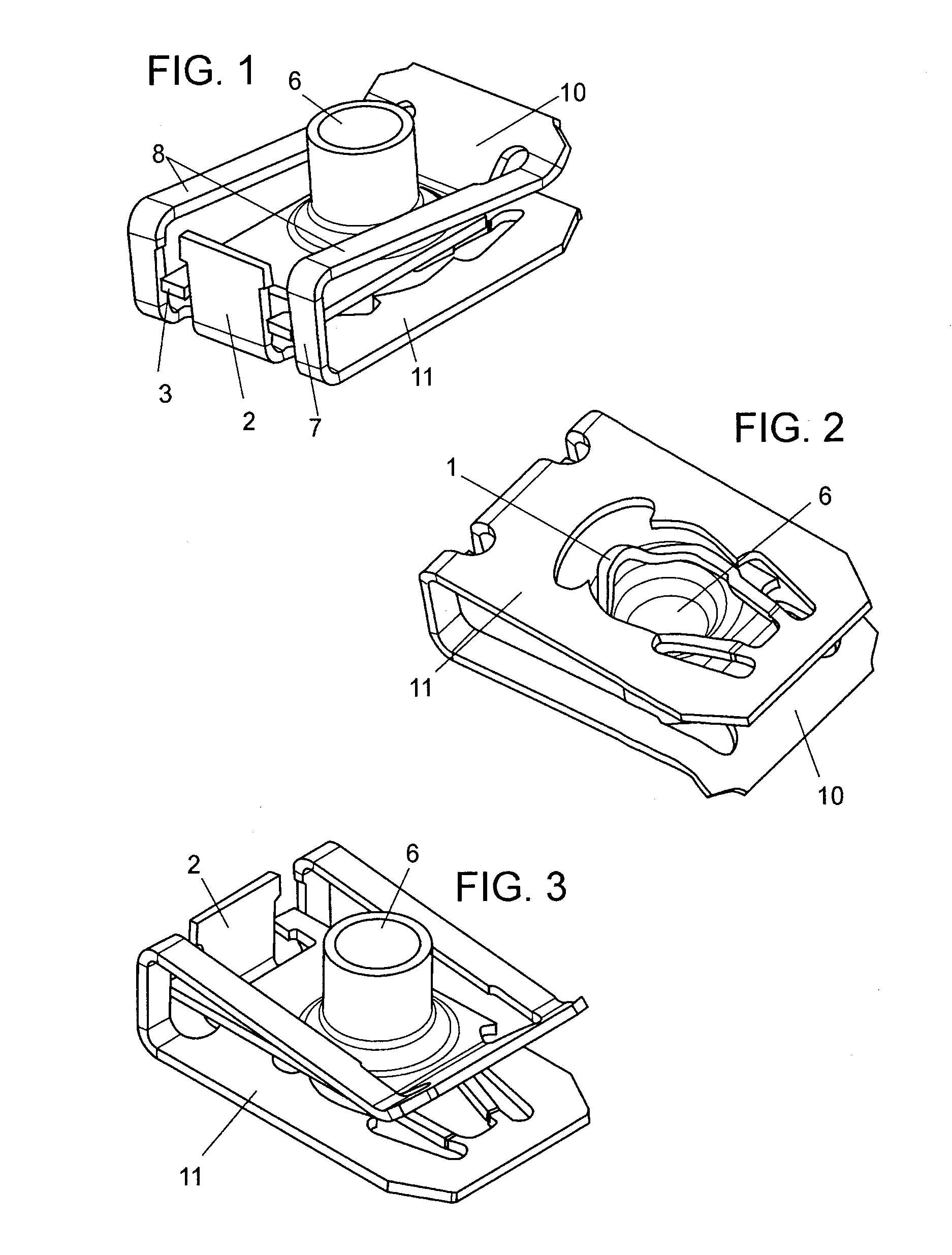
[0024]The present invention consists of a nut with a C-shaped profile, of the type formed by a punched metal sheet folded onto itself for fixing onto a panel, wherein one of the arms, i.e. the upper base (10) has, formed therein, a hole for the arrangement of a screwed device with at least one thread and wherein the other arm, i.e. the lower base (11) has, aligned with the axis of the preceding hole, another hole for receiving the screw for tightening the nut.

[0025]The nut according to the invention is preferably made of heat-treated tempered carbon steel. This feature means that it has the mechanical hardness and elasticity properties which are necessary and convenient for this type of product. In the same way it may be made of any type of material with hardness and elasticity properties which are suitable for the desired application.

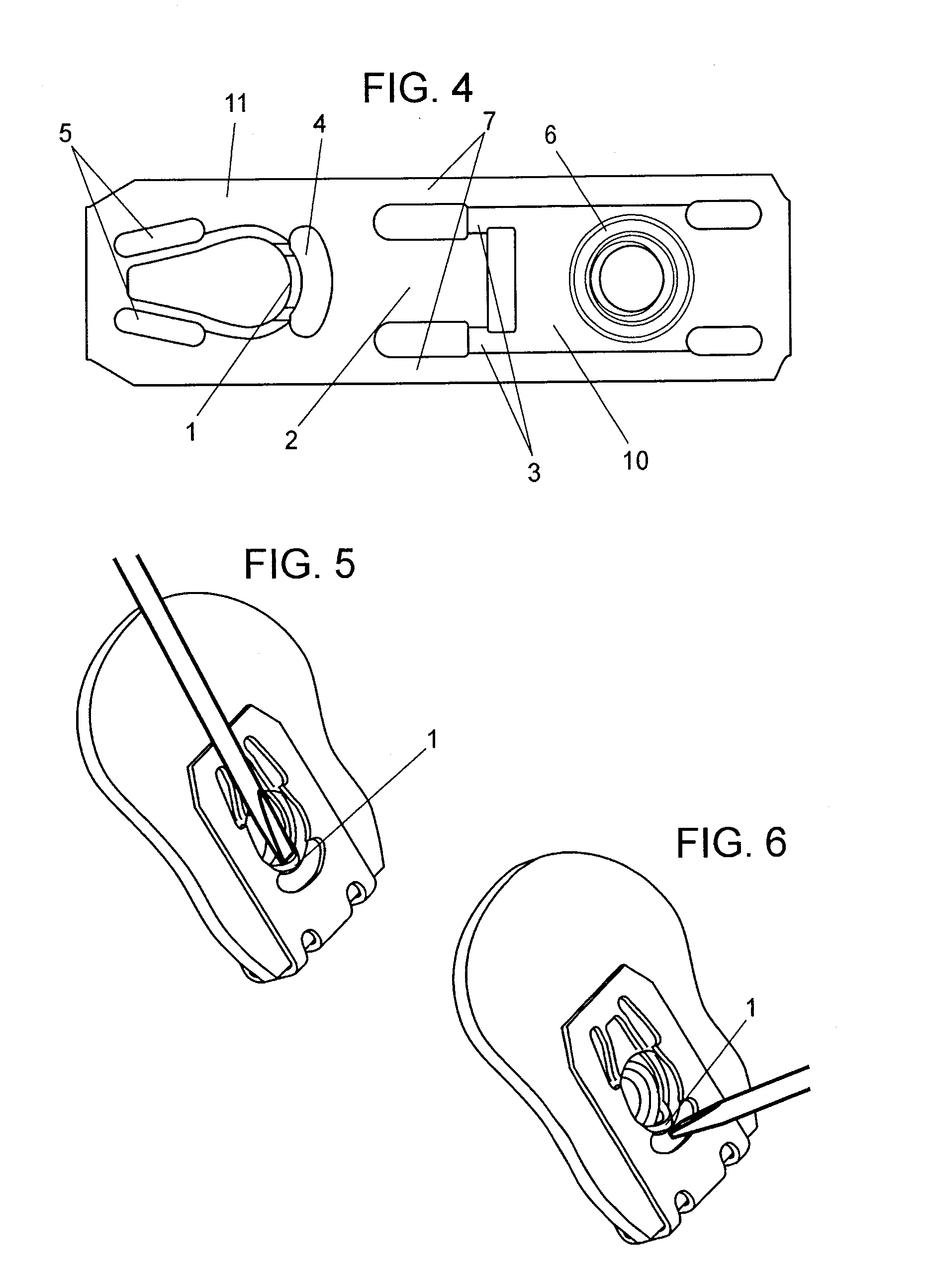
[0026]As shown in FIG. 4, the nut according to the invention may be obtained from a flat strip by means of deformation and punching so as to form all ...


PUM


Abstract

A NUT WITH A C-SHAPED PROFILE, of the type formed by a punched metal sheet folded onto itself for fixing onto a panel, wherein one of the arms, i.e. the upper base, has a hole for the arrangement of a screwed device with at least one thread and wherein the other arm, i.e. the lower base, which is aligned with the axis of the preceding hole, has another hole for receiving the nut tightening screw, said upper base being provided with incisions which define horizontal connecting portions separated from the body of said upper base and longitudinal connecting portions which form an extension of the former and which join together said upper base and lower base, which has a retaining claw which is designed to facilitate application of a tool for slackening the pressure which the nut applies to the panel to which it is fixed; which has a bottom rear flange and side stops on said upper base which form an anti-rotation mechanism when a screw is tightened on the nut; said bottom rear flange freeing from pressure said upper base during assembly on the panel; and said longitudinal connecting portions are overdimensioned, i.e. their height is greater than the sum of the greatest thickness “P” of the panel foreseen for use with said nut and the height “h” of said retaining claw in relation to said lower base.

Description

FIELD OF THE INVENTION[0001]The present invention relates to a nut with a C-shaped profile, of the type formed by means of punching of a flat strip which, folded in the manner of a clip, is mounted on a panel and which has a passage for a screw and at least a single thread for the screwed member, wherein a device for extracting the nut as well as other improvements to the clip nut are provided.PRIOR ART[0002]Clip nuts, various categories of which exist, are widely known in the art, the common feature of all of them being that they are formed by a metal sheet which is folded onto itself, said fold and the rigidity or elasticity thereof acting as a tensioning spring during fixing to the panel onto which it is mounted.[0003]For example, the known document ES1020704 describes a clip of this type where the nut is tightened by means of a screw which is mounted on a single thread formed by a helical profile in the upper strip of the clip. Said clip is provided with shaped incisions for fac...

Claims


Application Information

Patent Timeline
Patent Type & Authority Applications(United States)
IPC IPC(8): F16B37/02F16B39/00
CPCF16B37/041F16B37/02F16B5/00F16B37/04
Inventor TEJERO SALINERO, ISAAC
Owner ILLINOIS TOOL WORKS INC
Why Eureka
Try Eureka