Switch Pack Assembly for Cable Clusters of Network Switches and the Special Release Tool Assembly Thereof

a technology of network switches and tool assemblies, applied in the field of network switches, can solve the problems of oversized assembled structure, inconvenient operation, difficult and complex, etc., and achieve the effect of convenient and fast assembly, simple and practical structur

Inactive Publication Date: 2011-12-22
COMMSCOPE INC
View PDF7 Cites 17 Cited by
  • Summary
  • Abstract
  • Description
  • Claims
  • Application Information

AI Technical Summary

Benefits of technology

[0006]The object of the present invention is to overcome the problems and drawbacks of the prior art mentioned above. The present invention provides an improved switch pack assembly for cable clusters of network switches and the special release tool assembly thereof, which can achieve the operations of plugging and pulling a single cable arbitrarily and cables integrally. The present invention has simple and practical structures, is assembled conveniently and quickly, has stable and firm whole structures and a comprehensive application field.

Problems solved by technology

The intensive degree of cables on the switch can be imagined, and if one or one set of cables need to be plugged and pulled for debugging, it is very difficult and complex in the case of an unusual intensity of cables.
If the manipulation is improper, it will affect the communication quality of other cable interfaces, and may even lead to a wrong plug and pull, so as to result in communication failure.
(1) The first solution is that a set of (normally twelve) cables (usually connected with RJ45 standard interfaces) are assembled and fixed together with a simple frame and screws, then are plugged as a whole. A drawing tool specially equipped is needed for the pull operation. This structure only has the function of plugging and pulling cables as a whole, and lacks the function of plugging and pulling one separate cable. The drawing tool can not unlock specific sites. It can only press all cable snap-fit components down as a whole, and all cables can not be pulled out completely until all of them are unlocked and released. Therefore, not only the operation is inconvenient, but also the assembled structure is oversized, and the cost is relatively high.
(2) The second solution is that a set of cables are assembled and fixed together through a specific structure, which also has the function of plugging cables as a whole. No separate tool is needed to pull cables as a whole. The unlocking and pulling out the cables as a whole is achieved by using the clamping structure arranged at its end directly. Of course, this operation requires specific inner parts to cooperate. Thus, the resulting overall structure of the device is more complex, the cost is relatively high, and inevitably the volume of the device is relatively large. The device also has the function of plugging and pulling one separate cable, but in the operation of plugging and pulling cables individually, it is necessary to use a specific operational tool. For in the maintenance process of the switch, the operation of replacing some cables individually will be conducted frequently, while the operation of plugging and pulling the cables integrally will be seldom conducted. Unless in the processes of new installation, commissioning and replacement will it be possible to conduct such an operation, so the structure and function will cause inconvenience to users instead.

Method used


Image

  • Switch Pack Assembly for Cable Clusters of Network Switches and the Special Release Tool Assembly Thereof
  • Switch Pack Assembly for Cable Clusters of Network Switches and the Special Release Tool Assembly Thereof
  • Switch Pack Assembly for Cable Clusters of Network Switches and the Special Release Tool Assembly Thereof

Examples


Embodiment Construction

[0019]In order to understand the technical content of the present invention clearly, the present invention is further exemplified by reference to the following examples.

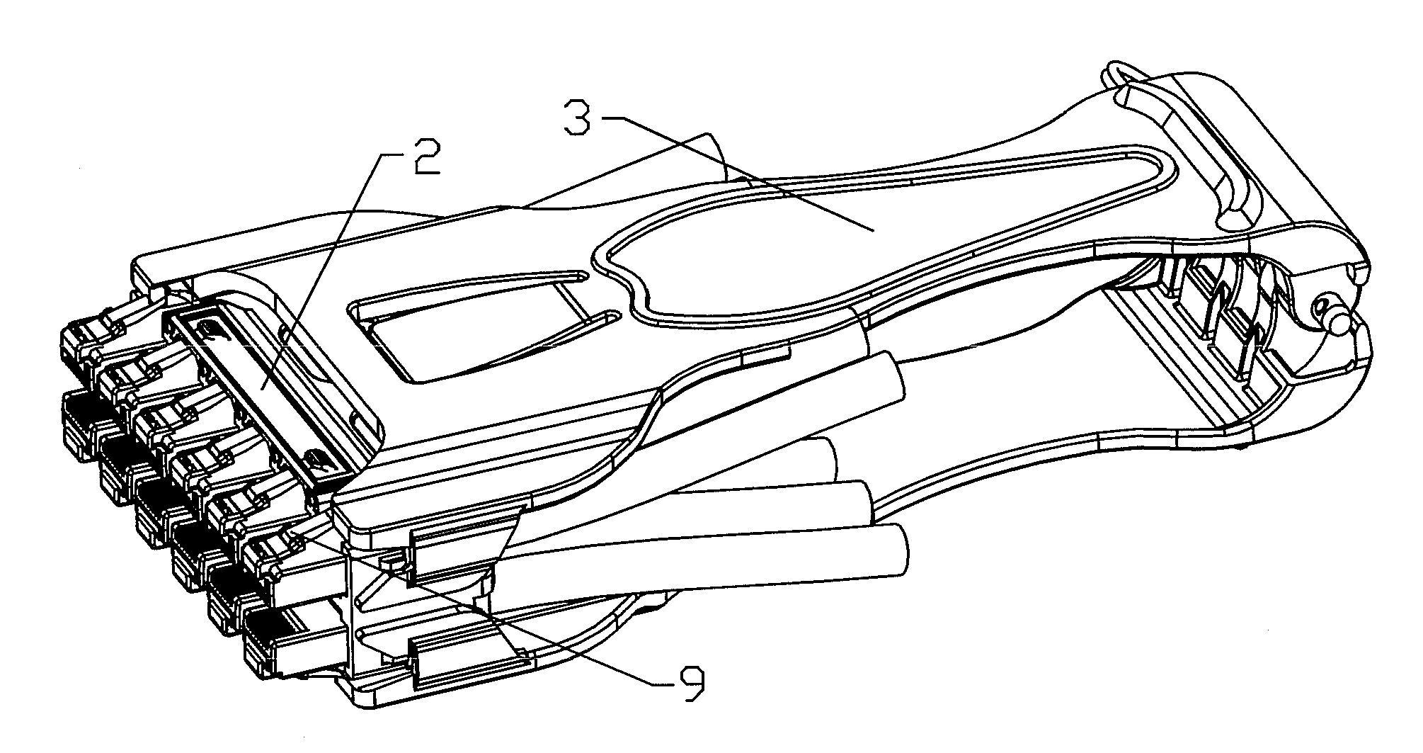
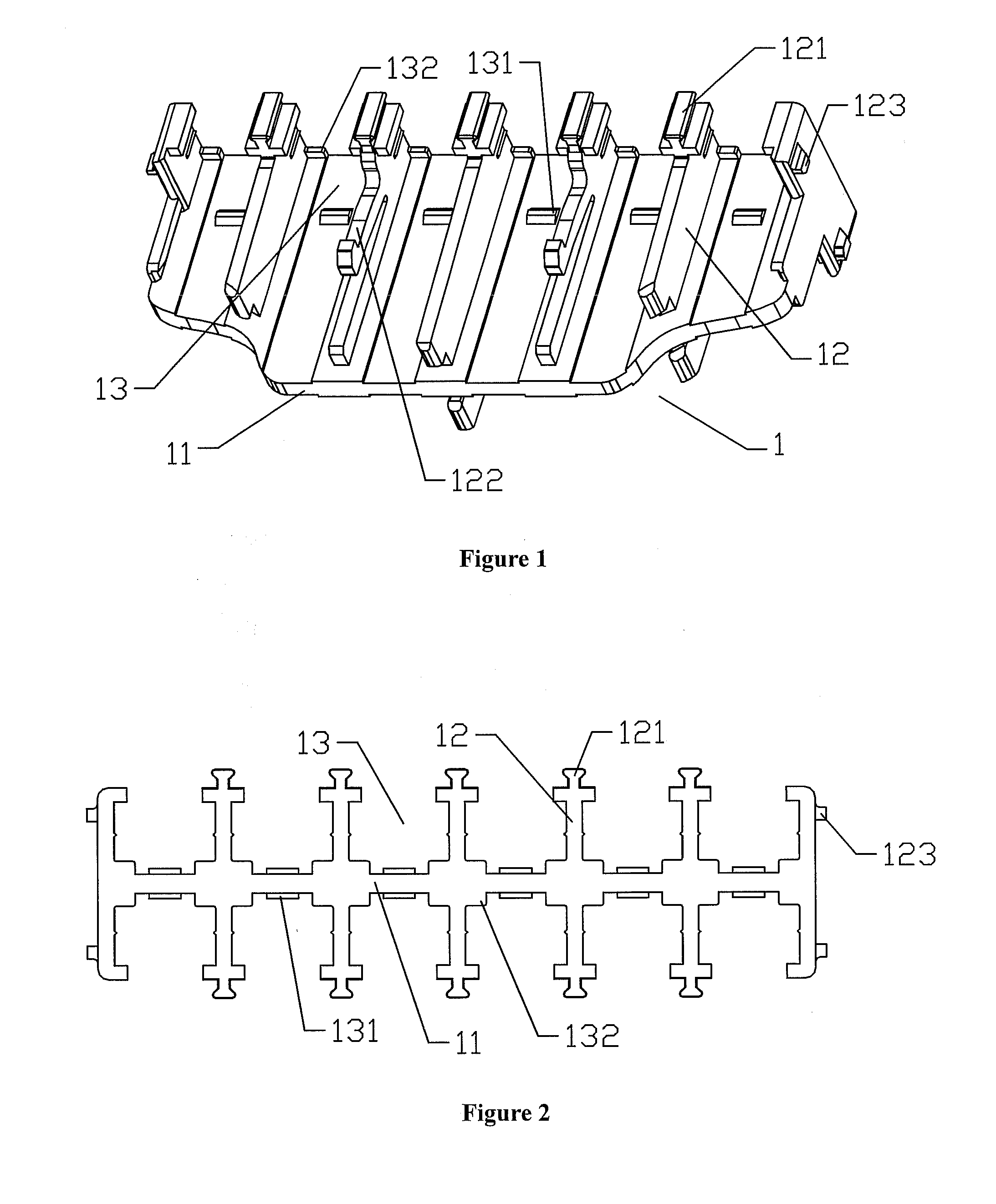
[0020]Referring to FIG. 1, FIG. 2 and FIG. 6, the switch pack assembly for cable clusters of network switches comprises a central framework 1 and two covers 2 arranged movably at two sides of the central framework 1, wherein several longitudinal parallel holding troughs 13 are arranged on the central framework 1.

[0021]The central framework 1 includes a central lateral substrate 11. On two side surfaces of the central lateral substrate 11 are arranged spaced from each other, several longitudinal clapboards 12. The longitudinal clapboards 12 are perpendicular to the central lateral substrate 11 and extend along the longitudinal direction. Each of the holding troughs 13 is formed between adjacent longitudinal clapboards 12. In accordance with one embodiment of the present invention, the longitudinal clapboards 12 are ar...


PUM


Abstract

A switch pack assembly for cable clusters of network switches includes a central framework and two covers arranged movably at two sides of the central framework. Several longitudinal parallel holding troughs are arranged on the central framework. The main body of the cover covers the holding troughs to form cavities. Open windows are arranged at positions on the cover corresponding to the front parts of at least one pair of cavities. A longitudinal sliding guide component and a pulling resisting component are arranged on the outside of the switch pack assembly and are designed to interact with a release tool. A shape of a front end of the release tool matches a shape of the switch pack assembly. At the front end of the tool are arranged unlocking pressure plates to interact with snap latches of plugs in the open windows. At the inside of the tool are arranged a longitudinal sliding positioning mechanism to interact with the sliding guide component and a pulling force-applying mechanism to interact with the pulling resisting component. With these structures, the operation of plugging and pulling cables as a whole is convenient and quick.

Description

TECHNOLOGY FIELD[0001]The present invention relates to the technical field of network switches, especially to the assembly structures for the plugs to mate to network switches, and the release of cables from network switches. In particular, the present invention relates to a switch pack assembly for cable clusters of network switches and the special release tool assembly thereof.BACKGROUND TECHNOLOGY[0002]In the modern society, with the continuous development of science and technology, the contacts between people are becoming closer increasingly. The constructions of communication infrastructure are becoming more perfect and progressive, so as to improve the communication process between people. For network switches at the core position of the network, a small switch only has a few dozen of cable interfaces, while a large switch has hundreds or even thousands of cable interfaces. The intensive degree of cables on the switch can be imagined, and if one or one set of cables need to be...

Claims


Application Information

Patent Timeline
Patent Type & Authority Applications(United States)
IPC IPC(8): H01R13/627H01R13/629
CPCH01R13/518H04Q2213/13003H01R43/26H01R13/60
Inventor LIU, JONYHU, GUANGHUI
Owner COMMSCOPE INC
Why Eureka
Try Eureka