
Plane floating clamp and floating structure thereof

A floating fixture and floating structure technology, applied in the field of machining fixtures, can solve the problems of complex structure, troublesome installation and high manufacturing cost, and achieve the effects of low manufacturing cost, convenient maintenance, simple and practical structure

Active Publication Date: 2016-11-16
湖南胤涛精密制造有限公司
View PDF9 Cites 7 Cited by
  • Summary
  • Abstract
  • Description
  • Claims
  • Application Information

AI Technical Summary

Problems solved by technology

[0003] Most of the existing floating fixtures for honing machines have complicated structures, such as the three-dimensional floating fixtures for high-precision CNC honing machines disclosed in the Chinese utility model patent whose publication number is CN201544114U, and the special plane floating fixtures for precision honing machines disclosed in the Chinese invention patent with the publication number CN104209860A. Fixtures, these floating fixtures rely on hydraulic pressure / spring force to control the floating of the workpiece, which is troublesome to install and expensive to manufacture

Method used


Image

  • Plane floating clamp and floating structure thereof
  • Plane floating clamp and floating structure thereof
  • Plane floating clamp and floating structure thereof

Examples


Embodiment Construction

[0037] In order to facilitate the understanding of those skilled in the art, the present invention will be further described below in conjunction with the embodiments and accompanying drawings.

[0038] In describing the present invention, it should be understood that the terms "length", "width", "upper", "lower", "front", "rear", "left", "right", "inner", " The orientation or positional relationship indicated by "outside", etc. is based on the orientation or positional relationship shown in the drawings, and is only for the convenience of describing the present invention and simplifying the description, rather than indicating or implying that the referred device or element must have a specific orientation, so as to Specific orientation configurations and operations, therefore, are not to be construed as limitations on the invention.

[0039] In addition, the terms "first" and "second" are used for descriptive purposes only, and cannot be interpreted as indicating or implying ...


PUM


Abstract

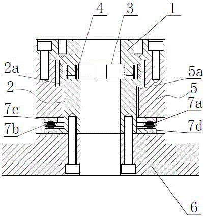
The invention provides a plane floating clamp and a floating structure thereof and relates to the technical field of machining clamps. The floating structure comprises a base A provided with two guiding columns, a base B provided with two guiding columns, and a floating block arranged between the base A and the base B and provided with a long-strip-shaped first guiding groove and a long-strip-shaped second guiding groove; the included angle between the first guiding groove and the second guiding groove is 90 degrees; the two guiding columns of the base A are inserted into the first guiding groove and can move back and forth in the length direction of the first guiding groove; and the two guiding columns of the base B are inserted into the second guiding groove and can move back and forth in the length direction of the second guiding groove. The plane floating clamp and the floating structure of the plane floating clamp are very simple in overall structure and has the beneficial effects of being convenient to install and low in manufacturing cost, and the plane floating clamp and the floating structure of the plane floating clamp are suitable for large-scale application and popularization.

Description

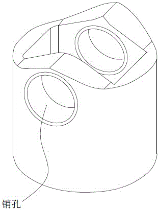
technical field [0001] The invention relates to the technical field of machining fixtures, in particular to a plane floating fixture and its floating structure. Background technique [0002] The roller body assembly is one of the key parts of the fuel injection pump. It is mainly composed of a roller body, a roller and a roller pin. There are two pin holes on the roller body (see figure 1 As shown), the coaxiality, dimensional accuracy and roughness of the pin hole play a decisive role in whether the product can finally meet the design requirements. In order to ensure the accuracy, the last finishing process of the pin hole is usually completed on a honing machine. During honing, the roller body is clamped by a floating fixture. [0003] Most of the existing floating fixtures for honing machines have complex structures, such as the three-dimensional floating fixtures for high-precision CNC honing machines disclosed in the Chinese utility model patent with the publication nu...

Claims


Application Information

Patent Timeline
IPC IPC(8): B24B33/10
CPCB24B33/10
Inventor 曾胤倡刘伟奇
Owner 湖南胤涛精密制造有限公司
Learn More