
Monitoring device and system

a technology of monitoring device and system, applied in the direction of electrical equipment, instruments, wireless commuication services, etc., can solve the problems of high cost and complexity of monitoring device, high cost of professional installation system, and complex array of systems

Inactive Publication Date: 2011-12-22
AUTHENTICATED SECURE MESSAGING
View PDF5 Cites 28 Cited by
  • Summary
  • Abstract
  • Description
  • Claims
  • Application Information

AI Technical Summary

Benefits of technology

[0012]It will be appreciated that embodiments of the present invention offer many advantages. They will be relatively cheap to manufacture and implement compared to complex centralised server based systems; they can be easily installed without needing any complex wiring or other infrastructure; fixings are not necessary; they could run off battery power if necessary (and could have some form of sleep function coming out of dormant mode only upon detection of a condition / event); they can be portable and taken away on holiday etc and they are simple to program and control.

Problems solved by technology

Monitoring devices vary considerably in cost and in complexity.
If you wish to install a security system to monitor your house or business, you are faced with a bewildering array of systems, all of which have different requirements and supporting infrastructures.
Not only are professionally installed systems expensive, they also are normally complex and provide many more features than the average user will ever use (or be able to work out how to use).
Some of the older systems operate over RF channels that actually overlap with the IEEE 802.11 channels and cause interference.

Method used


Image

  • Monitoring device and system
  • Monitoring device and system

Examples


Embodiment Construction

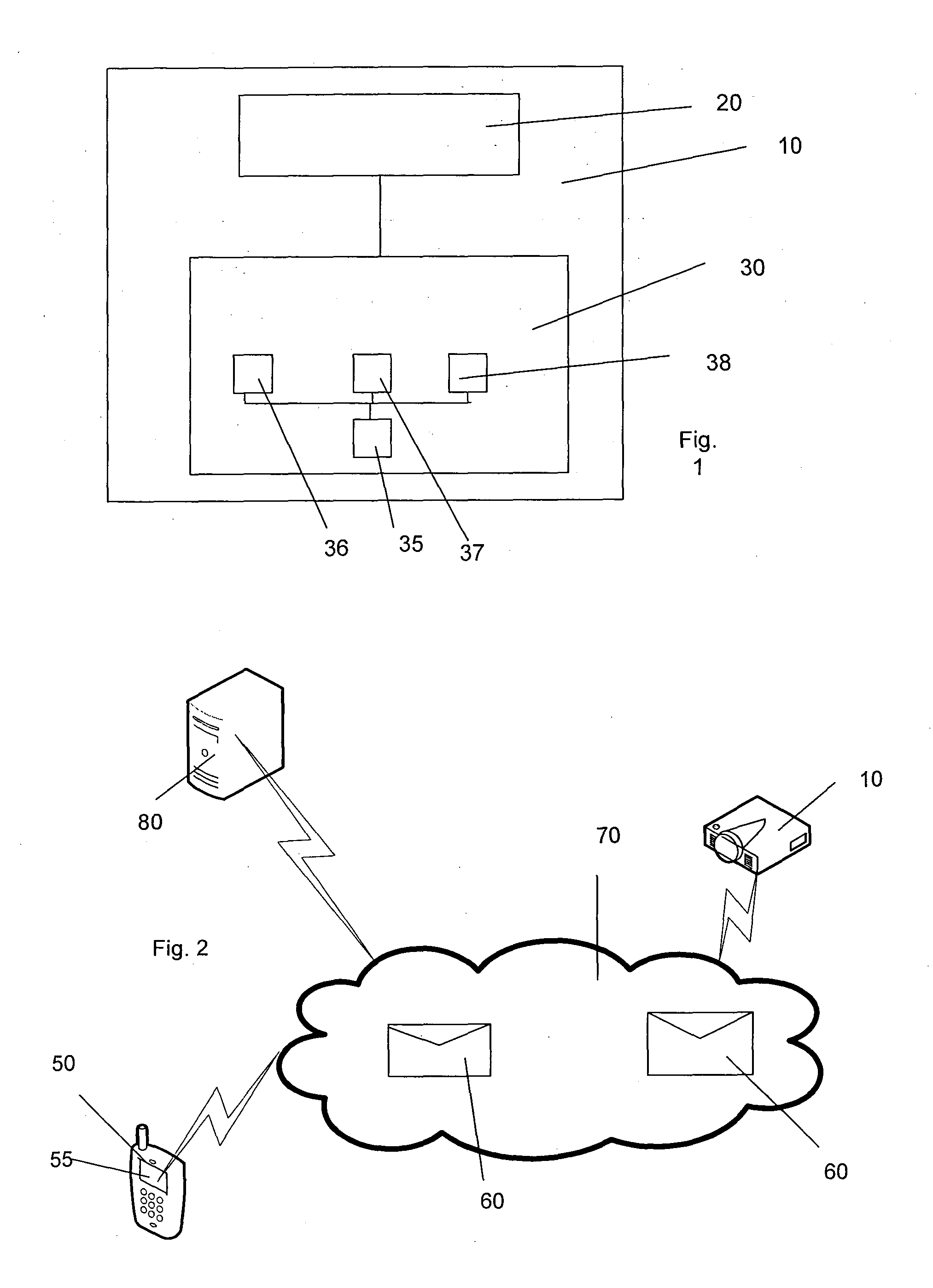
[0016]FIG. 1 is a schematic diagram of a monitoring device according to an embodiment of the present invention.

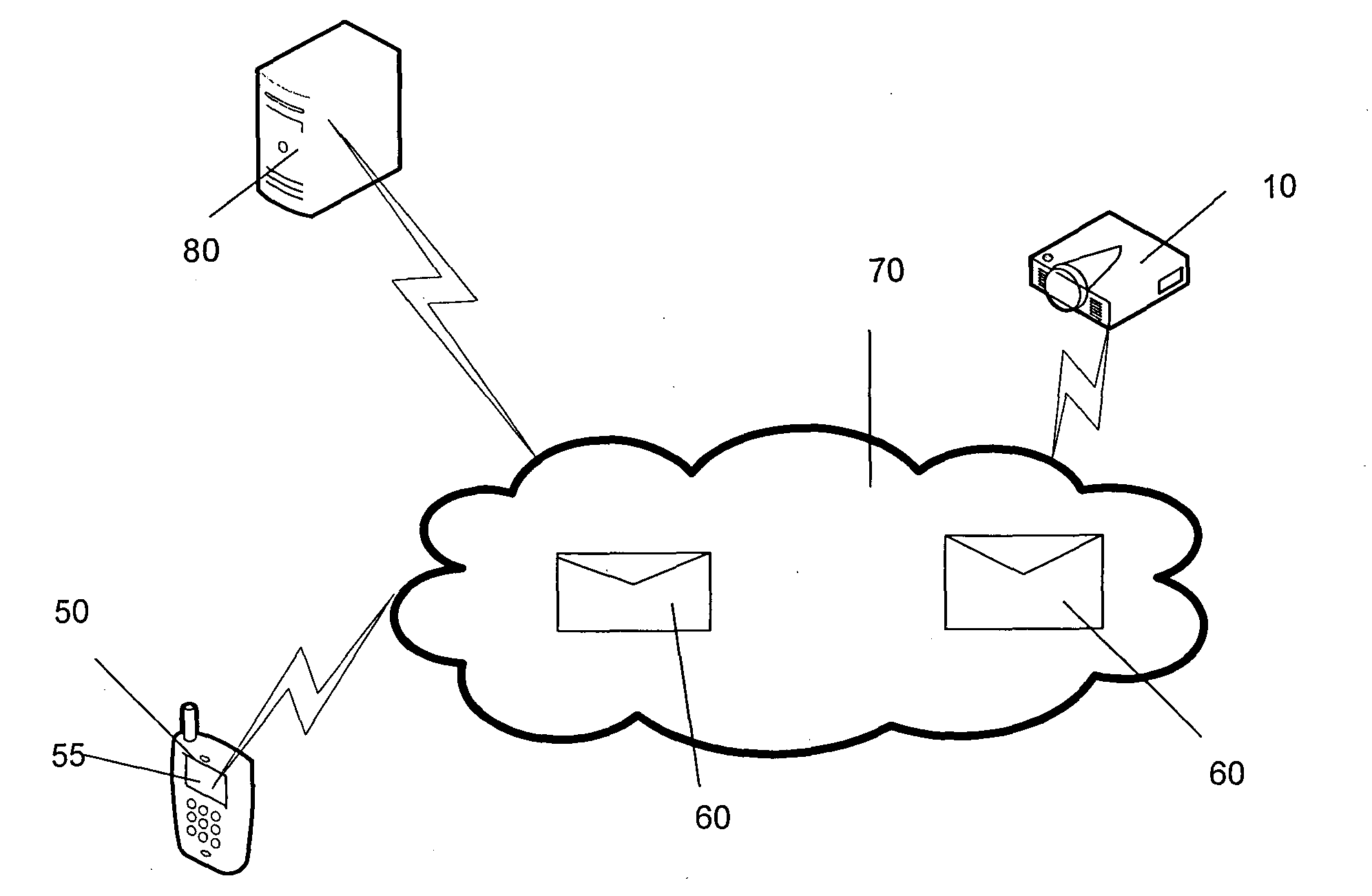
[0017]The monitoring device 10 includes a mobile communication component 20 and a monitoring component 30. The monitoring component 30 is arranged to cause transmission of a message to a predetermined recipient system via said mobile communication component 20 upon detection of a predetermined condition or event.

[0018]In a preferred embodiment, the monitoring component 30 includes a camera 35 and the message includes an image associated with the condition or event captured by the camera and embedded within the message. In a preferred embodiment, the mobile communication component 20 is a mobile telephony device. Preferably, the message comprises a multimedia message (MMS).

[0019]The monitoring component 30 may also include components such as an infra-red detector 36, a motion detector 37, a microphone 38 or the like for use in detecting the condition or event that triggers t...


PUM


Abstract

A stand-alone monitoring device and system are disclosed. The device comprises a mobile communication component operable to communicate over a communications network and a monitoring component, wherein the monitoring component is arranged to cause transmission of a message over said communications network to a predetermined recipient system via said mobile communication component upon detection of a predetermined condition or event.

Description

FIELD OF THE INVENTION[0001]The present invention relates to a monitoring device and system that is particularly applicable in situations where low cost, simple security monitoring is desired and / or there is little or no ability to install cabling and other infrastructure to support the device.BACKGROUND TO THE INVENTION[0002]Monitoring devices vary considerably in cost and in complexity. They range from basic audio baby monitoring systems to complex home or business alarm systems.[0003]If you wish to install a security system to monitor your house or business, you are faced with a bewildering array of systems, all of which have different requirements and supporting infrastructures. Many people resort to professionally installed systems so that they have the reassurance that the system works correctly and that someone else is responsible for installation, configuration and cleaning up the mess.[0004]Not only are professionally installed systems expensive, they also are normally comp...

Claims


Application Information

Patent Timeline
Patent Type & Authority Applications(United States)
IPC IPC(8): H04W4/14
CPCG08B13/196
Inventor AGERHOLM, SOREN
Owner AUTHENTICATED SECURE MESSAGING
Learn More