Disposable suture cutter

Active Publication Date: 2011-12-22
LINVATEC
View PDF3 Cites 7 Cited by
  • Summary
  • Abstract
  • Description
  • Claims
  • Application Information

AI Technical Summary

Benefits of technology

[0008]A suture cutter made in accordance with one embodiment of the present invention includes features resulting in a

Problems solved by technology

As mentioned briefly above, suture materials typically become harder to cut as their strength increases.
Unfortunately, medical professionals are not typically provided with the luxury of having such a large are required to use such large tools, especially during laparoscopic and arthroscopic procedures.
Because the sharpness of the knife edge reduces mo

Method used


Image

  • Disposable suture cutter
  • Disposable suture cutter
  • Disposable suture cutter

Examples


Embodiment Construction

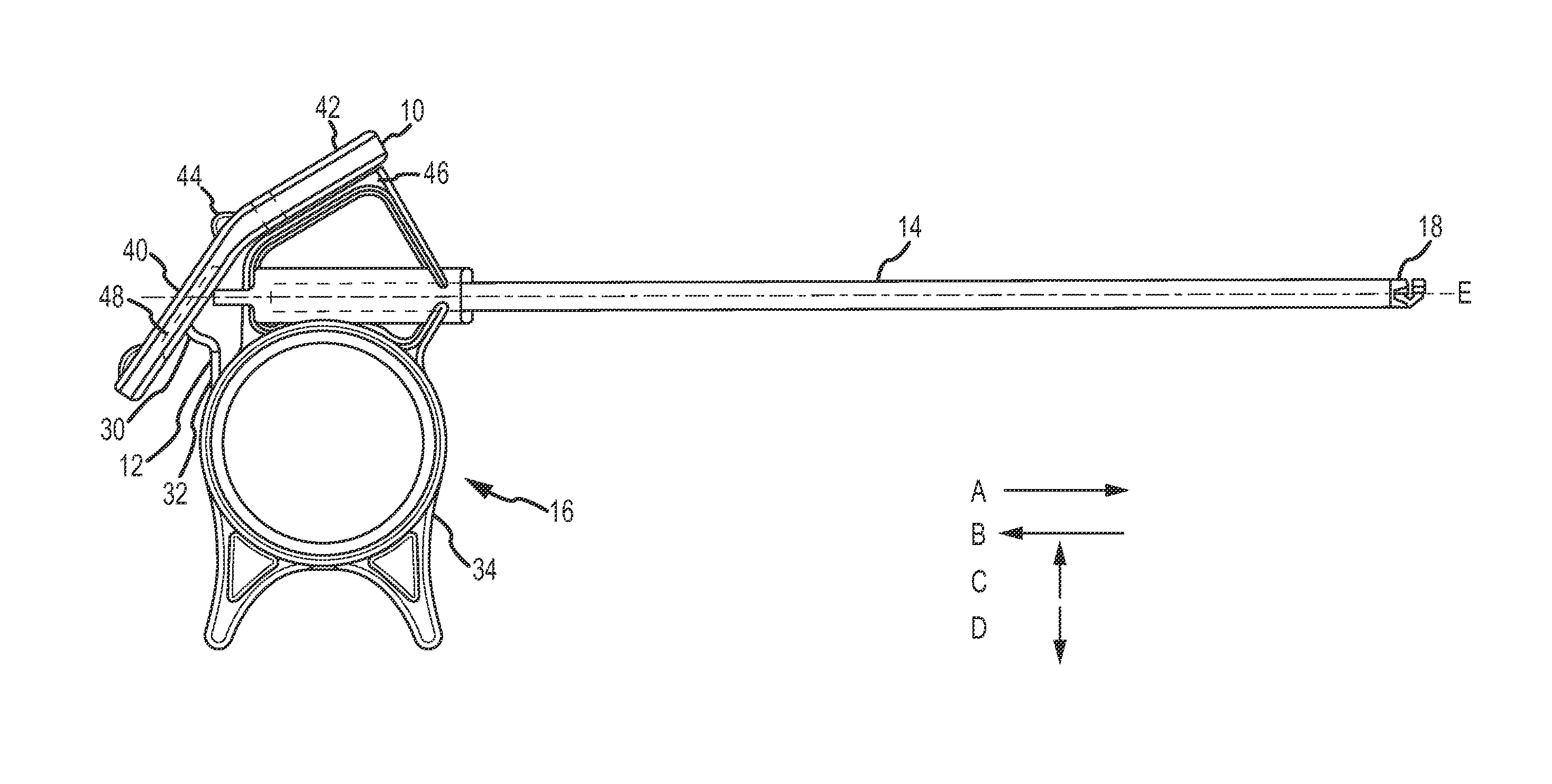
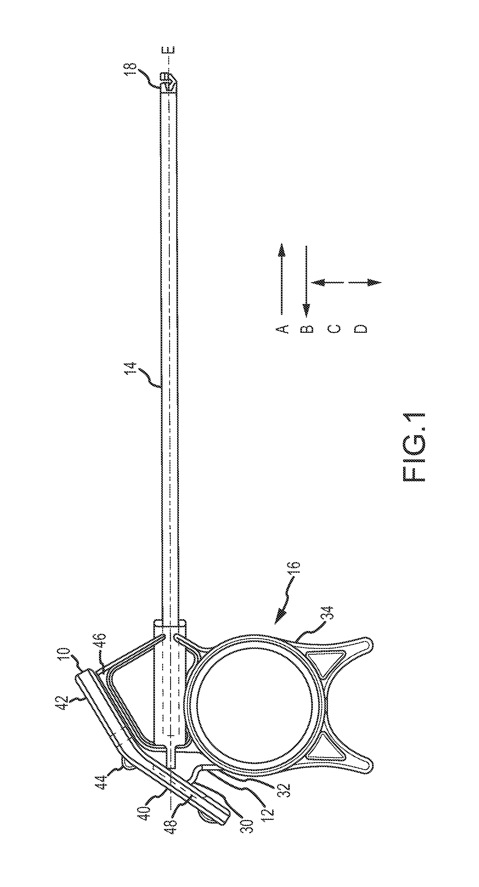
[0017]A suture cutter device made in accordance with one embodiment of the present invention is represented in FIG. 1. For the purposes of the present description the relative directions “A”, “B”, “C”, and “D” represented in FIG. 1 are defined as follows: the direction “A” will be referred to as “distal” or “distally”; the direction “B” will be referred to as “proximal” or “proximally”; the direction “C” will be referred to as “dorsal” or “dorsally”; and the direction “D” will be referred to as “ventral” or “ventrally”. Further, the general longitudinal axis of the device is represented in FIG. 1 as axis “E”.

[0018]Throughout the present description and figures, like reference numbers are used to identify similar features across all of the figures.

[0019]An embodiment of the present invention represented in FIG. 1 includes a hollow shaft 14 extending along longitudinal axis E. A handle 16 is positioned at a proximal end of the hollow shaft 14 and a suture guide 18 is positioned at a d...


PUM


Abstract

A suture cutting device is provided, the device suitable for cutting high strength suture materials used in arthroscopic surgeries. The device includes a distal blade portion movable within a distal suture guide, the distal suture guide including a lateral suture guide slot. The distal blade portion includes a dorsal recess that, in combination with an upper wall of an enclosed blade guide slot, controls an amount of dorsal movement of a cutting edge during a longitudinal movement of the cutting edge. The combined dorsal movement and longitudinal movement of the cutting edge creating a sliding/slicing movement of the cutting edge against a suture in the suture guide slot. At least a proximal blade portion and an extension blade portion are made of a single blade, those portions defining a spring, contacting a trigger, and effectuating a movement from a first position to a second position.

Description

TECHNICAL FIELD OF THE INVENTION[0001]This invention relates to the design and use of a surgical instrument. The present invention relates particularly to a disposable surgical suture cutting device that is capable of cutting high strength sutures at a distance from a surgeon's hand and in confined spaces, such as during an arthroscopic surgery.BACKGROUND OF THE INVENTION[0002]Surgical sutures are used as part of nearly every surgical procedure. Even though the medical industry typically uses the generic term “suture” to describe a filament used in these surgical procedures, suture material varies greatly depending on the task to be accomplished.[0003]Looking at sutures from a broad perspective, the strength of available suture materials varies greatly. For example, suture material used to dose and hold together tissue does not need to be much, if any, stronger than the surrounding tissue. Due at least in part to their relatively low material strength, these suture materials are oft...

Claims


Application Information

Patent Timeline
IPC IPC(8): A61B17/10
CPCA61B17/320016A61B17/0467
Inventor MILLER, PETER C.
Owner LINVATEC
Why Eureka
Try Eureka