Partially self-erecting wind turbine tower

a wind turbine and self-erecting technology, applied in the direction of machines/engines, mechanical equipment, building repairs, etc., can solve the problems of increasing the overall increasing the cost of the installation of the wind turbine, and limiting the access of large machinery

Inactive Publication Date: 2011-12-29
GEE ANTHONY F
View PDF32 Cites 13 Cited by
  • Summary
  • Abstract
  • Description
  • Claims
  • Application Information

AI Technical Summary

Benefits of technology

[0013]With the pylon and legs thus temporarily secured, a nacelle is attached to the upper extreme of the telescoping pylon. A hub with attached blades is affixed to the nacelle. The telescoping pylon is then forced upward through the collar to extend the height of the assembly. The telescoping pylon is raised to its operational position with its lower extreme being affixed to the collar. By raising the telescoping pylon, the nacelle and attached hub and blades are positioned an appropriate distance above the ground.

Problems solved by technology

The foundation is generally cast from concrete, and the use of such a large structure adds to the overall cost of the wind turbine installation.
Prior art wind turbines are quite large.
Such wind turbines are typically installed in remote locations, where access for large machinery is limited.
Transporting extremely large cranes to such sites represents a substantial portion of the total cost of installing a wind turbine.

Method used


Image

  • Partially self-erecting wind turbine tower
  • Partially self-erecting wind turbine tower
  • Partially self-erecting wind turbine tower

Examples


Embodiment Construction

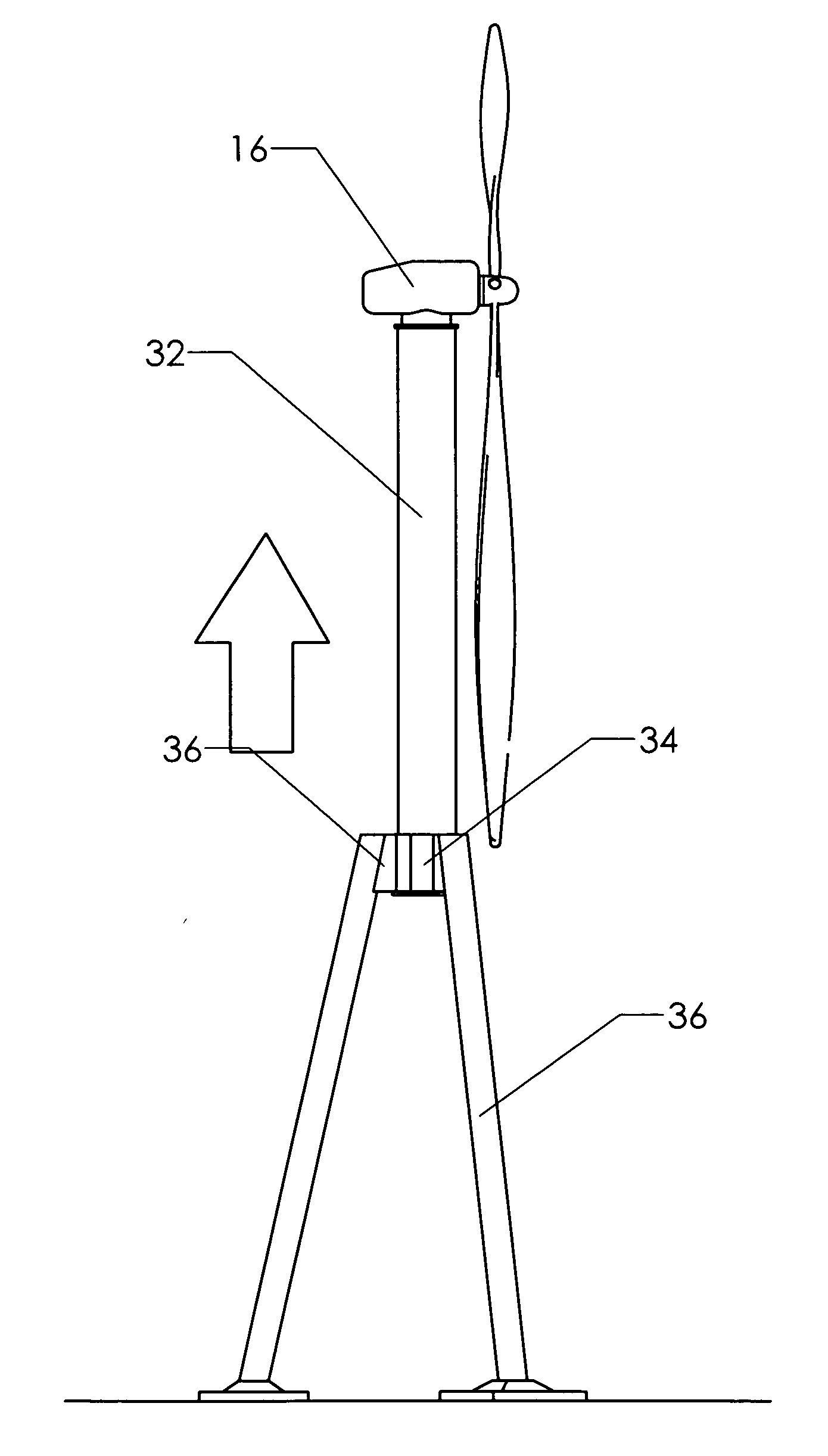
[0030]FIG. 3 shows an embodiment of a wind turbine constructed according to the present invention. The support structure includes telescoping pylon 32, which is supported by a plurality of legs 36. Rather than having a single unified foundation, a split foundation 38 is furnished for the base of each leg 36.

[0031]The upper portion of each leg 36 is preferably attached to a collar 34, which surrounds telescoping pylon 32. The collar may formed by uniting portions of the legs themselves, or it may be a separate structure to which the legs are attached. Whatever form it takes, the collar provides a sliding attachment between the legs and telescoping pylon 32, so that the telescoping pylon can move up and down with respect to the legs.

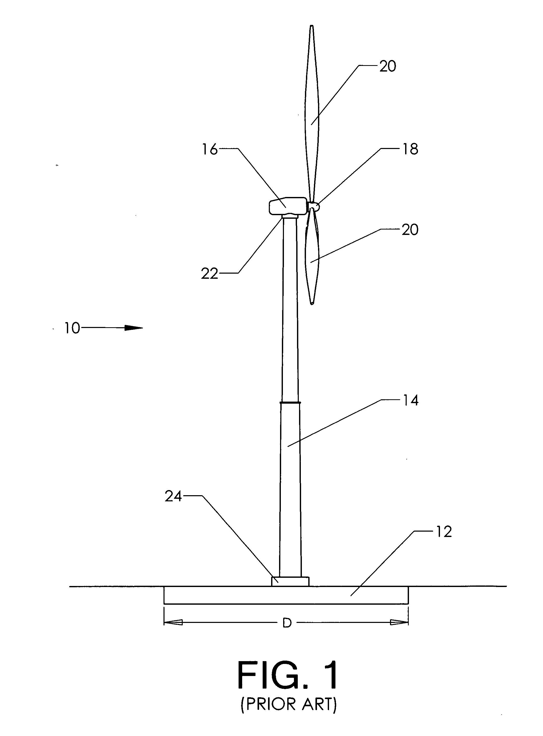
[0032]The upper portions of the assembly shown are the same as those found in the prior art. Nacelle 16 is attached to the upper portion of the telescoping pylon by yaw joint 22. Hub 18 is attached to the nacelle. Blades 20 are attached to the hub.

[0033]Th...


PUM


Abstract

A partially self-erecting wind turbine tower and a method for carrying out the assembly thereof. A central telescoping pylon is provided. This is placed in an upright position, with its base on a temporary foundation. A plurality of legs is then attached to the telescoping pylon. The upper extreme of each of the plurality of legs is temporarily attached to the upper extreme of the telescoping pylon. With the pylon and legs thus secured, a nacelle is attached to the upper extreme of the telescoping pylon. A hub with attached blades is then affixed to the nacelle. The telescoping pylon is then forced upward through the collar to extend the height of the assembly.

Description

CROSS-REFERENCES TO RELATED APPLICATIONS[0001]Not applicable.STATEMENT REGARDING FEDERALLY SPONSORED RESEARCH OR DEVELOPMENT[0002]Not ApplicableMICROFICHE APPENDIX[0003]Not ApplicableBACKGROUND OF THE INVENTION[0004]1. Field of the Invention[0005]This invention relates to the field of wind energy production. More specifically the invention comprises a partially self-erecting wind turbine tower which significantly reduces the lift height required for assembly of the components.[0006]2. Description of the Related Art[0007]FIG. 1 depicts a prior art wind turbine 10. Pylon 14—which may include two or more joined segments—is affixed via base 24 to foundation 12. Nacelle 16 houses a revolving horizontal shaft to which hub 18 and blades 20 are attached. The nacelle typically also contains a gearbox for stepping up the rotational speed of hub 18, a generator for converting the rotating shaft energy to electrical energy, control electronics, and a braking mechanism (which may be mechanical, ...

Claims


Application Information

Patent Timeline
Patent Type & Authority Applications(United States)
IPC IPC(8): E04H12/34E04H12/00
CPCE04H12/34Y02E10/728F05B2240/9151F03D1/001F03D13/10Y02E10/72
Inventor GEE, ANTHONY F.
Owner GEE ANTHONY F
Why Eureka
Try Eureka