Nail printing apparatus

a printing apparatus and nail technology, applied in printing presses, typewriters, printing, etc., to achieve the effect of preventing a change in posture or movement, not producing discomfort, and not producing pain in the printing target finger

Inactive Publication Date: 2011-12-29
CASIO COMPUTER CO LTD
View PDF12 Cites 14 Cited by
  • Summary
  • Abstract
  • Description
  • Claims
  • Application Information

AI Technical Summary

Benefits of technology

[0010]This invention is derived from the above-described circumstances, an object of the present invention is to provide a nail printing apparatus that does not produce discomfort like a sense of pressure in a print target finger of a user, does not produce pain in the print target finger even if the print target finger is unintentionally and suddenly moved, and can prevent a change in posture or movement from occurring in the print target finger placed on the print target finger stage.

Problems solved by technology

Furthermore, as different from a conventional nail printing apparatus, the at least one finger with the nail, on which the desired image is to be printed, of the one hand placed on the print target finger placing surface is not restrained by a restraint instrument.

Method used


Image

  • Nail printing apparatus
  • Nail printing apparatus
  • Nail printing apparatus

Examples


Embodiment Construction

One Embodiment

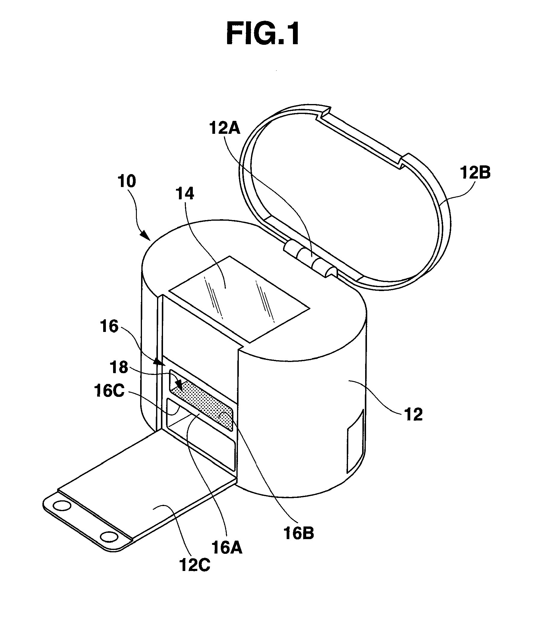
[0029]FIG. 1 schematically shows an appearance of a nail printing apparatus 10 according to one embodiment of the present invention.

[0030]An outer housing 12 of the nail printing apparatus 10 has an upper surface, a bottom surface, and a circumferential surface which connects the upper surface with the bottom surface. The outer housing 12 comprises an upper lid 12B coupled with the upper surface through a hinge 12A to be freely openable and closable and a front lid 12C coupled with a front part of the circumferential surface through a non-illustrated hinge to be freely openable and closable.

[0031]A control panel 14 including various switches and a display for a control unit configured to control operations of various structures of an internal configuration accommodated in an inner space of the outer housing 12 is arranged on the upper surface of the outer housing 12. The control panel 14 is covered with the upper lid 12B located in its closed position, and the control ...


PUM


Abstract

A nail printing apparatus is provided with a main body including a held portion which has a print target finger placing surface and a non-print-target finger placing surface. The print target finger placing surface is configured in such a manner that at least one finger with a nail, on which a desired image is to be printed, of one hand is placed thereon. The non-print-target finger placing surface is configured in such a manner that at least one remaining finger of the one hand is placed thereon. The held portion is held between the at least one finger on the print target finger placing surface and the at least one remaining finger on the non-print-target placing surface. The apparatus is further provided with an image printing unit configured to print the desired image on the nail of the at least one finger on the print target finger placing surface.

Description

CROSS-REFERENCE TO RELATED APPLICATIONS[0001]This application is based upon and claims the benefit of priority from prior Japanese Patent Applications No. 2010-144545, filed Jun. 25, 2010; No. 2010-144552, filed Jun. 25, 2010; and No. 2010-144554, filed Jun. 25, 2010, the entire contents of all of which are incorporated herein by reference.BACKGROUND OF THE INVENTION[0002]1. Field of the Invention[0003]The present invention relates to a nail printing apparatus used for printing a desired image on a nail.[0004]2. Description of the Related Art[0005]A conventional nail printing apparatus comprises a print target finger stage on which a finger with a nail on which a desired image is to be printed (which will be referred to as a print target finger hereinafter) is placed at a predetermined position, and a printing unit that prints the desired image on the nail of the print target finger placed at the predetermined position on the print target finger stage.[0006]When the print target fin...

Claims


Application Information

Patent Timeline
Patent Type & Authority Applications(United States)
IPC IPC(8): B41F17/00
CPCA45D29/00B41J3/4073B41J3/407A45D2029/005
Inventor BITOH, HIROYASU
Owner CASIO COMPUTER CO LTD
Why Eureka
Try Eureka