

Working component for mating with multiple shaft ends
a technology of working components and output shafts, which is applied in the direction of manufacturing tools, mechanical equipment, and power-driven tools. it can solve the problems of not having good commonality of existing working components, different working components of different brands cannot be used commonly, and working components of other brands cannot be mounted to his own multi-functional tools. it reduces the number of accessories, reduces manufacturing costs, and is easy to carry
- Summary
- Abstract
- Description
- Claims
- Application Information
AI Technical Summary
Benefits of technology
Problems solved by technology
Method used
Image

Examples
first embodiment
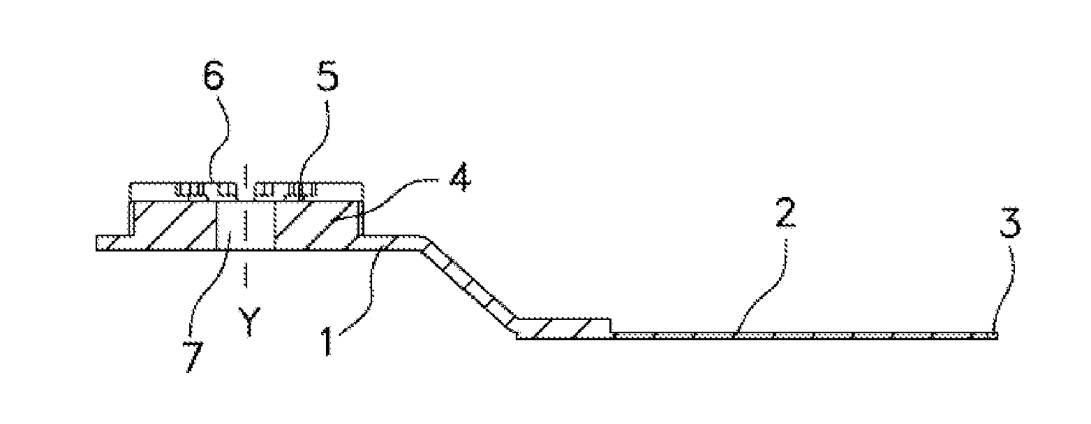
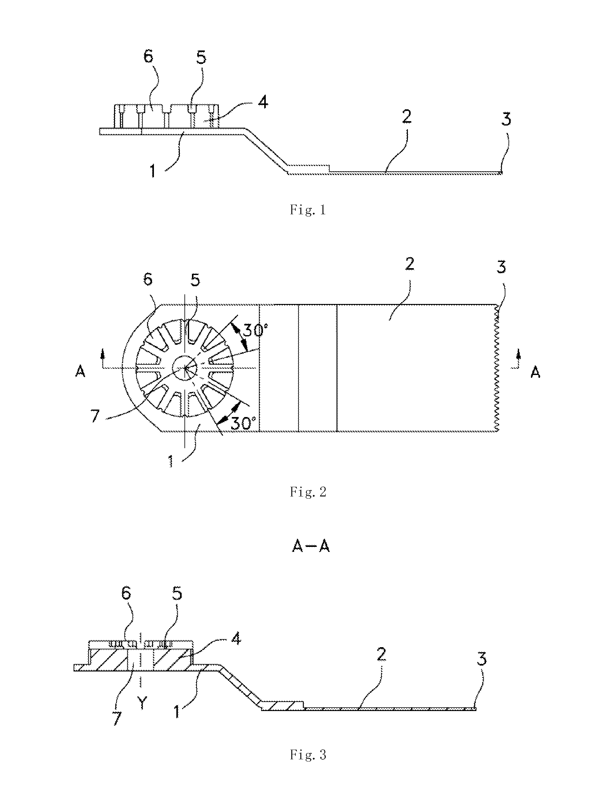
As shown in FIGS. 1-7, a saw blade commonly used as a working component with an oscillating tool is illustrated as a The saw blade includes a body portion 2 and a clamping portion which is connected to the body portion 2 and suitable for mating with the shaft end of the multifunctional tool. The front end of the body portion 2 includes a saw teeth area 3 which may act on the work piece to be processed for cutting. The clamping portion for connecting the saw blade to the shaft end of the tool includes a support portion 1 and a mating portion 4. The mating portion 4 is formed integrally with the support portion 1. Certainly, in other embodiments, the mating portion 4 may be fixedly connected to the support portion 1 by welding, riveting, bolt or other connections. A plurality of grooves 5 and a plurality of projections 6 radially extending through one another are arranged radially and alternately on the end surface of the mating portion 4 (for clarity, only one groove and one project...
second embodiment
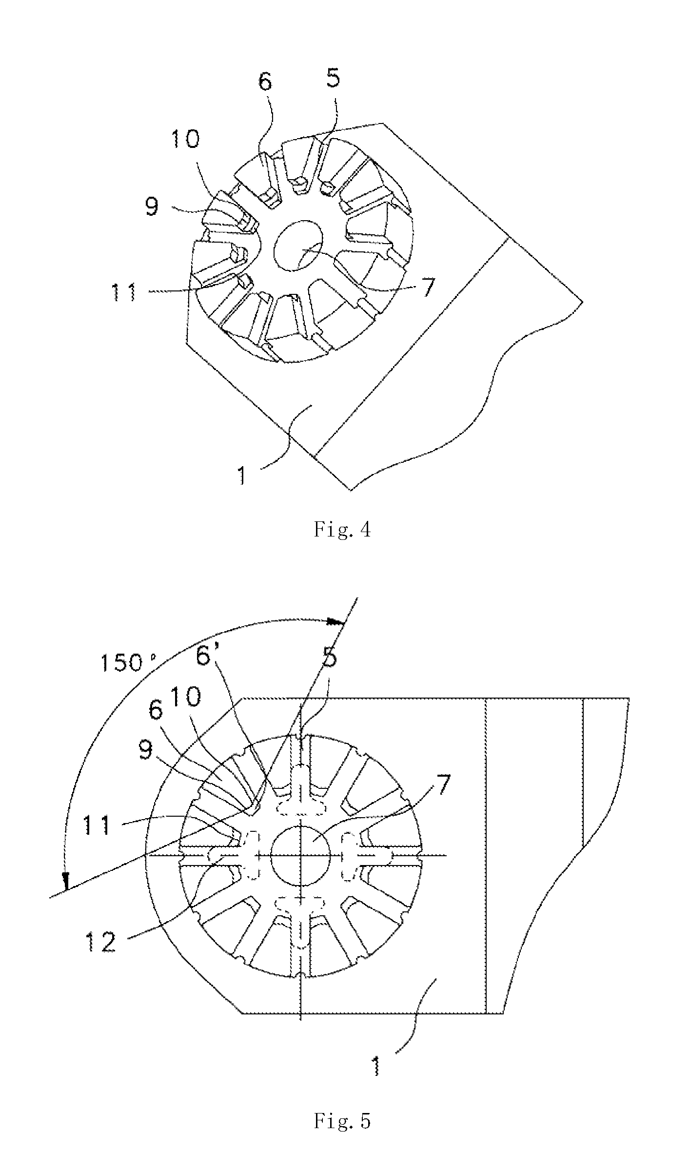
In the second embodiment, the support portion 1 and the mating portion 4 of the saw blade are welded together by spot welding. In order to align the positioning hole 310 with the mounting hole 7 exactly in the welding, a tiny projection 220 is formed on the support portion 1 by a stamping process along the longitudinal axis Y. The projection 220 is projected towards the end surface on which the mating portion 4 is welded, an outer edge of the projection 220 and an edge 310′ of the positioning hole 310 are substantially the same in shape and size.
The specific welding process will be explained as follows: firstly, the mating portion and the support portion are centered with each other exactly; then, the positions of the welding joints are determined, and at least one circle of the welding joints 40 are positioned on the multiple projections 6 formed between each two adjacent grooves 5. In the oscillating tools, the projections 6 formed between the grooves 5 on the mating portion are m...
fourth embodiment
The mating structure of the mating portion 4, the mounting structure of the support portion 1 and the welding connection process between the mating portion 4 and the support portion 1 are the same as those in the fourth embodiment, and thus will not be explained in details herein.
As shown in FIGS. 22-24, a sixth embodiment differs from the fourth embodiment in that the support portion 1 is further provided with concave portions 110 formed by a stamping process. The concave portions 110 are distributed on the whole circumference and correspond to the bottoms of the grooves 5 of the mating portion which are far away from the longitudinal axis Y. With this arrangement, the thickness of the mating portion 4 may be relatively thinner, and when the height of the projections on the shaft end of the multifunctional tool is larger than the thickness of the mating portion 4, the difference may be offset by the depth of the concave portions 110, that is to say, the projections of the shaft end...
PUM
 Abstract
Description
Claims
Application Information